Wave Phenomena Single Slit Diffraction
advertisement
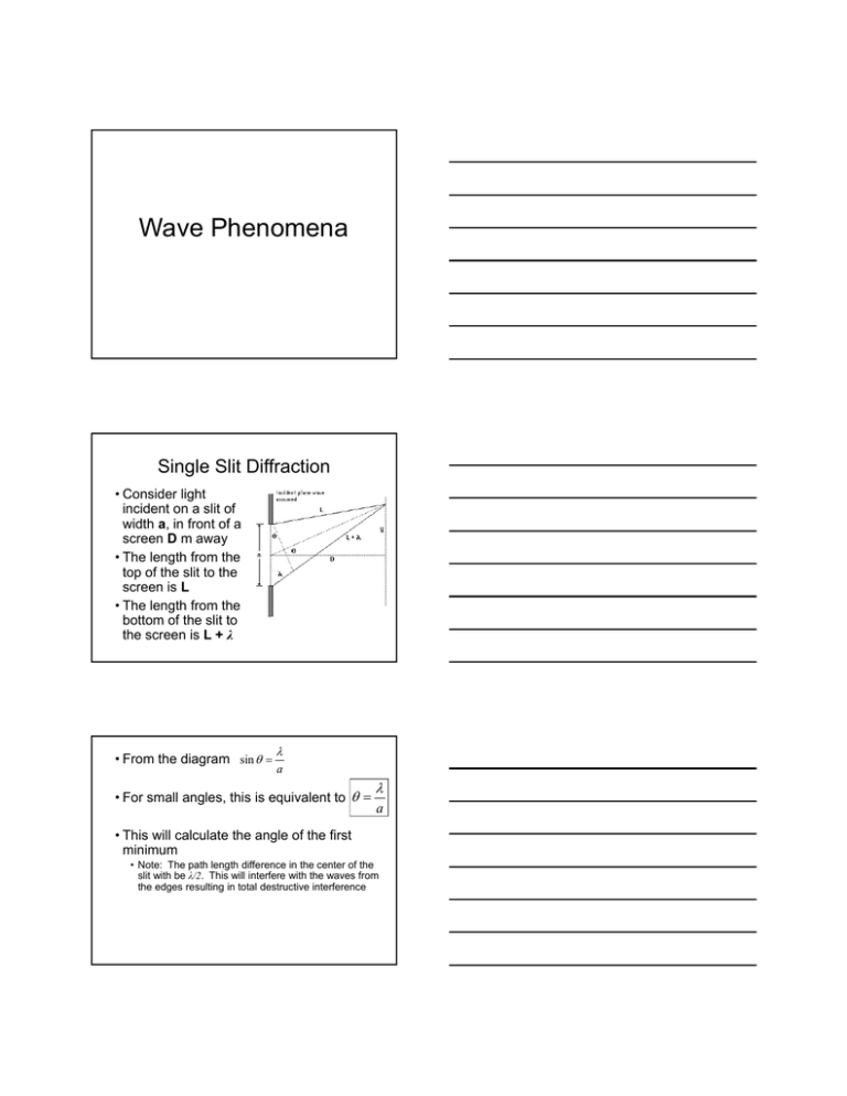
Wave Phenomena Single Slit Diffraction • Consider light incident on a slit of width a, in front of a screen D m away • The length from the top of the slit to the screen is L • The length from the bottom of the slit to the screen is L + λ • From the diagram sin a • For small angles, this is equivalent to a • This will calculate the angle of the first minimum • Note: The path length difference in the center of the slit with be λ/2. This will interfere with the waves from the edges resulting in total destructive interference Example • Light of wavelength 550 nm is incident on a slit of width 1.5 μm. Calculate the width of the central maximum. b 550 10 9 m 0.37 radians 1.5 10 6 m Central maximum = 0.74 radians Double Slit Interference • The path difference between the two slits is dsinθ • For the point y to be a bright fringe (constructive interference) the path difference must be λ • Therefore dsinθ=λ y • From the diagram tan D • For small angles (measured in radians), sinθ=tanθ=θ • Therefore y d D • Rearranging gives y D d Example • Monochromatic light is incident on a double slit with spacing of 0.50 mm. The bright fringes are spaced 2.5 mm apart on a screen 2.0 m away. What is the wavelength of the light? s D d sd (2.5 10 3 m)(0.5 10 3 m) 6.25 10 7 m D 2.0 m Diffraction Grating • When light is incident on a diffraction grating it produces interference maxima at angles θ given by n d sin n is the “order” of the maximum (zero for the central maximum, 1 for the first maximum on each side of the center, etc.) cnx.org/contents/031da8d3-b525-429c-80cf6c8ed997733a@8.32:217/College_Physics • The spacing between the slits is small, which makes the angle θ large for a fixed wavelength and n • Therefore we cannot use the small angle approximation • A diffraction grating usually gives the lines per mm, N, instead of the distance between the lines • This value must be converted to spacing, d, to use the diffraction grating equation d 1 N Example • A diffraction grating having 600 lines per mm is illuminated with a parallel beam of monochromatic light normal to the grating. This produces a second order maximum which is observed at 42.5° to the straight through direction. Calculate the wavelength of the light. n d sin d 1 1.67 10 6 m 600(1000) d sin (1.67 10 6 m) sin( 42.5) n 2 5.63 10 7 m Thin Films • When light is incident on the thin film it is both reflected and refracted at the surface • The reflected light undergoes a phase shift of π radians www.ualberta.ca/~pogosyan/teaching/PHYS_130/FALL_2010 /lectures/lect34/lecture34.html • The refracted light pass through the thin film a distance of nd where n is the index of refraction and d is the thickness of the film • The light then partially reflects off the bottom of the film and passes through the film again before reflecting and refracting from the top surface • Therefore the total path length of the light in the film is 2dn • Normally the path difference required for constructive interference is λ • However, in the case of a thin film, the reflected ray undergoes a phase change of π radians • This is equivalent to a path difference of λ/2 • Therefore destructive interference will occur when the path length differs by λ and constructive interference will occur when the path length differs by λ/2 • Therefore we can state Constructive interference : 2dn m 12 Destructive interference : 2dn m Example • A film of oil (n=1.45) floats on a layer of water (n=1.33) and is illuminated by light at normal incidence. When viewed from near normal incidence a particular region of the film appears red with an average wavelength of about 650 nm. Calculate the average thickness of the film. 2dn m 12 d m 12 12 (650 109 m) 1.1107 m 2n 2(1.45) Resolution • Light from a distant star will, upon passing through a circular aperture, diffract • If the two sources are close, we have a hard time deciding if there are two sources or just one • If the sources are far apart, they are said to be “resolved” – We can easily tell that there are two sources Rayleigh Criterion • The two sources are just resolved if the central maximum of the diffraction pattern of one source falls on the first minimum of the other Resolution Equation • For a linear slit, the first minimum occurs at b • For a circular aperture of diameter b, the first minimum occurs at 1.22 b Example • A student observes two distant point sources of light of wavelength 550 nm. The angular separation as seen by the student is 2.5x10⁻⁴ radians. Calculate the diameter of the of the student’s pupil if the images are just resolved. 1.22 b 1.22 b 1.22(550 10 9 m) 2.7 10 3 m 2.5 10 4 radians Diffraction Gratings • Diffraction grating are used to separate light of different colors • The more lines (slits) we have, the better the resolution will be • The resolvance, R, for a diffraction grating is defined as the ratio of the wavelength of light λ to the smallest difference in wavelength that can be resolved by the grating Δλ • The resolvance is also equal to mN where N is the total number of slit illuminated by the incident beam and m is the order of the diffraction R mN • The larger the resolvance, the better a device can resolve Example • Two lines in the emission spectrum of sodium have wavelengths of 589.0 nm and 589.6 nm. Calculate the number of lines per mm needed by a diffraction grating if the lines are to be resolved in the second order spectrum with a beam of width 0.10 mm. R N m 589.0nm (586.6 589.0nm)2 N 490.8 or mN N m 589.6nm (589.6 589.0nm)2 N 491.3 N is the number of lines illuminated by the beam that is 0.1 mm wide. We need the number of lines per mm. 490.8 4908 lines per mm .1mm 491.3 4913 lines per mm .1mm Note: Diffraction gratings are not usually sold with this number of lines per mm. A normal amount would be 5000 lines per mm. Doppler Effect • When there is relative motion between a source of waves and an observer, the observed frequency of the waves is different to the frequency of the source of the wave Stationary Source • Sound waves are produced at a constant frequency f0, and the wavefronts propagate symmetrically away from the source at a constant speed v • The distance between wavefronts is the wavelength. • All observers will hear the same frequency, which will be equal to the actual frequency of the source Moving Source • A source producing the same frequency as before is moving to the right • The center of each new wavefront is now slightly displaced to the right • The wavefronts begin to bunch up on the right side (in front of) and spread further apart on the left side (behind) of the source • An observer in front of the source will hear a higher frequency f ´ > f0, and an observer behind the source will hear a lower frequency f ´ < f0 • The frequency that the observer hears is calculated as follows: v f ' f v u s Source is moving with speed us Moving Observer • If the sound source is stationary and the observer is moving the same effect happens • The apparent frequency increases as the observer moves towards the source • The apparent frequency decreases as the observer moves away from the source • The frequency heard by the observer in this case is calculated as follows: v uo f ' f v Observer is moving with speed uo Light • Light waves are also susceptible to the Doppler effect • If the source (or observer) is traveling at a speed much less than the speed of light we can approximate the observed change in frequency (or wavelength) as follows: f v f c Standing (Stationary) Waves Standing Waves • Under the right circumstances waves can be formed in which the positions of the crests and the troughs do not change • Two travelling waves of equal amplitude and equal frequency travelling with the same speed in opposite directions are superposed • This is a standing wave Special Terms • Node – Points where the displacement is always zero • Antinode – Displacement is a maximum – Note: the maximum is not always the same maximum Harmonics • We can have different modes of vibration or harmonics • The first mode of vibration has the lowest frequency and is called the first harmonic. • The next modes of vibration are the second harmonic, third harmonic,… • Each harmonic is an interval of the fundamental – f2 = 2f1 – f3 = 3f1 – f4 = 4f1 Standing Waves on a String • There is a node at each end where the string is attached. • First harmonic (fundamental) L f1 v 1 f1 1 2 1 2 L v 2L • Second harmonic L f2 v 2L 2 2 2 f2 22 2 2v 2 f1 2L • Third harmonic L f3 v 3 f3 33 2 3 2L 3 3v 3 f1 2L Standing Waves in an Open Pipe • An open pipe (open at both ends) behaves similarly to a string • First harmonic (fundamental) 1 L 2 v f1 1 2 L 1 f1 v 2L • Second harmonic L f2 v 2L 2 2 2 f2 22 2 2v 2 f1 2L • Third harmonic L f3 v 3 f3 33 2 3 2L 3 3v 3 f1 2L Standing Waves in a Closed Pipe • A pipe that is closed at one end has a node at the closed end and an antinode at the open end • First harmonic (fundamental) 1 L f1 4 v 1 4 L 1 f1 v 4L • Third harmonic L f3 v 3 f3 33 4 3 3v 3 f1 4L 4L 3 • Fifth harmonic L f5 v 5 f5 55 4 5 5v 5 f1 4L 4L 5
