THE DESIGN OF AN INTER-DIGITAL STRUCTURE FOR TWTS TH5.2
advertisement

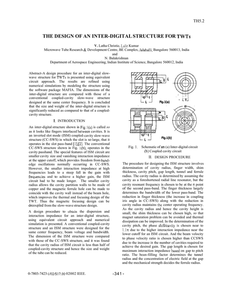
TH5.2 THE DESIGN OF AN INTER-DIGITAL STRUCTURE FOR TWTS V. Latha Christie, Lalit Kumar Microwave Tube Research & Development Centre, BE Complex, Jalahalli, Bangalore 560013, India and N. Balakrishnan Department of Aerospace Engineering, Indian Institute of Science, Bangalore 560012, India Abstract-A design procedure for an inter-digital slowwave structure for TWTs is presented using equivalent circuit approach. The results are refined using numerical simulations by modeling the structure using the software package MAFIA. The dimensions of the inter-digital structure are compared with those of a conventional coupled-cavity slow-wave structure designed at the same center frequency. It is concluded that the size and weight of the inter-digital structure is significantly reduced as compared to that of a coupledcavity structure. L T ~ 1. INTRODUCTION An inter-digital structure shown in Fig.l(a) is called so as it looks like fingers interlaced between cavities. It is an inverted slot mode (ISM) coupled-cavity slow-wave structure (CC-SWS) in which the slot is so large, that it operates in the slot pass-band [1],[2]. The conventional CC-SWS structure shown in Fig. I(b), operates in the cavity passhand. The special features of ISM circuit are smaller cavity size and vanishing interaction impedance at the upper cutoff, which provides freedom from bandedge oscillations normally occurring in CC-SWS. However, the smaller interaction impedance at high frequencies leads to a steep fall in the gain with kequencies and to achieve a higher gain, the ISM circuit had to be made longer. The smaller cavity radius allows the cavity partition walls to be made of copper and the magnetic ferrule hole can be made to coincide with the cavity wall instead of the beam hole, which improves the thermal and focusing design of the TWT. Thus the magnetic focusing design can be decoupled from the slow-wave structure design. A design procedure to obtain the dispersion and interaction impedance for an inter-digital structure, using equivalent circuit approach and numerical simulation is presented. A conventional coupled-cavity structure and an ISM structure were designed for the same center frequency, beam voltage and bandwidth. The dimension of the ISM structure were compared with those of the CC-SWS structure, and it was found that the cavity radius of ISM circuit is less than half of coupled-cavity structure and hence the size and weight of the tube can be reduced. 0-7803-7423- 1/02/$17.00 02002 IEEE. Fig. 1. Schematic of an (a) Inter-digital circuit (b) Coupled cavity circuit 11. DESIGN PROCEDURE The procedure for designing the ISM structure involves determination of cavity radius, finger width, shim thickness, cavity pitch, gap length, tunnel and ferrule radius. The cavity radius is determined by assuming the cavity as a foreshortened radial line resonator, but the cavity resonant frequency is chosen to be at the x point of the second pass-band. The finger thickness largely determines the bandwidth of the lower pass-band. The reduction in finger thickness (the increase in coupling iris angle in CC-SWS) along with the reduction in cavity radius maintains the center operating frequency. As the cavity radius and hence the cavity height is small, the shim thickness can be chosen high, so that magnet saturation problem can be avoided and thermal dissipation can be improved. In the determination of the cavity pitch, the phase shiwcavity is chosen near to I.lx due to the higher interaction impedance near the lower cutoff for an ISM circuit. And the beam velocity to phase velocity ratio is chosen higher than CCSWS due to the increase in the number of cavities required to achieve the desired gain. The gap length is chosen for maximum interaction impedance based on gap to pitch ratio. The bean-filling factor determines the tunnel radius and the concentration of electric field at the gap and the mechanical strength decides the ferrule radius. -341 - - ZPE -


