Technical Data
BMS Pro – BMS Interface
Catalog#
Prepared by
Project
Date
Comments
Type
Overview
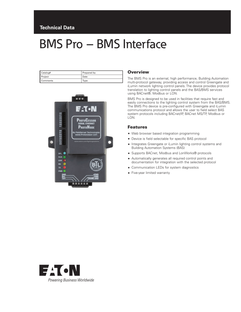
The BMS Pro is an external, high performance, Building Automation
multi-protocol gateway, providing access and control Greengate and
iLumin network lighting control panels. The device provides protocol
translation to lighting control panels and the BAS/BMS services
using BACnet®, Modbus or LON.
BMS Pro is designed to be used in facilities that require fast and
easily connections to the lighting control system from the BAS/BMS.
The BMS Pro device is pre-configured with Greengate and iLumin
communications protocol and allows the user to field select BAS
system protocols including BACnet/IP, BACnet MS/TP, Modbus or
LON.
Features
Web browser based integration programming
Device is field selectable for specific BAS protocol
Integrates Greengate or iLumin lighting control systems and
Building Automation Systems (BAS)
Supports BACnet, Modbus and LonWorks® protocols
Automatically generates all required control points and
documentation for integration with the selected protocol
Communication LEDs for system diagnostics
Five-year limited warranty
BMS Pro – BMS Interface
December 2015
Specifications
Supported
Serial (RS-485)
Protocols
Supported
Ethernet
Protocols
Supported
Electrical
Connections
Power
Requirements
Operating
environment
Dimensions
Approvals
Warranty
Description and Operation
The BMS Pro provides up to 10,000 points of control and can
communicate to multiple panel types on the lighting control
network. Each BMS Pro can be programmed to communicate to
either a Greengate or iLumin network and a single Ethernet access
point (either the EIM or EG2-NA).
BACnet MS/TP Modbus RTU
BACnet IP Modbus TCP/IP
(1) 6 pin Phoenix Connector
(1) RS-485 +/- Ground port Power +/- Frame
Ground port
(1) Ethernet -10/100 Ethernet port
(1) FTT-10 LonWorks port (LonWorks Version)
9-30 VDC or 12-24VAC Current draw @ 12V = 240
mA
Indoor use only
-40°C to 75°C (-40°F to 167°F)
Relative humidity (non-condensing): 5% to 90%
4.52 x 3.25 x 1.60 inches (LxWxH) / (11.49 x 8.25 x
4.06 cm)
BACnet Testing Labs (BTL) B-ASC
LonMark 3.4 Certified
TUV approved to UL 916 standard and CSA C22-2
For Greengate lighting control networks the BMS Pro will
automatically find all network lighting control panels and prepopulate the BACnet, Modbus, or LON points of control for each
panel.
For iLumin lighting control networks uploading the iLumin Virtual
Area file will load the Areas, Scenes and Channels programmed into
the system. These are automatically mapped to BACnet, Modbus or
LON points of control.
The BMS Pro uses a 9-30VDC power input and can be powered
from auxiliary power generated from most lighting control panels. If
auxiliary power is not available a separate power supply should be
provided.
Catalog #
FPC-N341130
(supports
BACnet,
Modbus
BAS/BMS
protocols)
Five-year limited
Dimensions
Total
Point
Capacity
Network
Series
Greengate
10,000
iLumin
3.25"
FPC-N351131
(Supports
LON BAS/
BMS
protocol)
4.52"
Ethernet
connection to
building LAN
1.6"
(Depth)
2
Power
Connection
www.eaton.com/lightingsystems
Greengate
4,096
iLumin
Panel Supported
Room Controller
ControlKeeper 2
ControlKeeper 4
ControlKeeper 4A
ControlKeeper T
ControlKeeper M/ MB
SCUN
SCUN-FT
SCRP
SCRPB
Room Controller
ControlKeeper 2
ControlKeeper 4
ControlKeeper 4A
ControlKeeper T
ControlKeeper M/ MB
SCUN
SCUN-FT
SCRP
SCRPB
Point
Count Per
Panel
115
161
161
181
213
225
Based on
imported
Virtual
Area file
115
161
161
181
213
225
Based on
imported
Virtual
Area file
BMS Pro – BMS Interface
December 2015
Wiring Diagram
Building LAN
(provided by others)
BAS/BMS
Communicating BACnet/IP
or LON
Dimmer 2
Blue - EM Line In
0-10V Dimming Outputs
+ + + Dimmer 3
Dimmer 1
Dimmer 3
+
-
Dimmer 2
+
-
QuickConnect Cables
Integration Controls
High End
Not Used
3
4
Reset
Occ
Vac (default)
20%
Energy
Options
Occupancy
2
1
Default 10%
0-10V Gain
Adjustment
40%
Status
Low End
30%
Dimmer 2
Dimmer 1
-
Dimmer 2
+
-
Adjustable Skylights
Switchpack
Black
Green
Receptacle
BMS/Out
Dimmer 1
-
+
Sensors
Sensors
Slider
Station
5
Wallstations
+
+
+
A/V
Mode
+
Demand
Response
Alert
Mode
Time
Clock
6
QuickConnect Cables
White
Red
4
3
2
1
Occupancy
Not Used
3
2
4
Occ
Vac (default)
Reset
1
20%
Energy
Options
Energy Options DIP Switch
Demand Response
Default 10%
30%
Status
40%
0-10V Dimming Outputs
+ + + Dimmer 3
Dimmer 2
Dimmer 1
+
Adjustable Skylights
Adjustable Skylights
Integration Controls
Blue - Load In
Yellow - Load 1 Out
0-10V Gain
Adjustment
40%
Status
Low End
30%
1
Energy Options DIP Switch
Demand Response
0-10V Gain
Adjustment
4
Energy
Options
Not Used
3
Occ
Vac (default)
High End
Occupancy
2
Reset
20%
Black - Line In
White/Black - 120V N
White/Orange - 277V N
Black - Line In
1
1
Default 10%
CAUTION: Bonding between conduit connections is not automatic and must be provided as part of the installation.
Red - Load 2 Out
Purple - Load 3 Out
2
Energy Options DIP Switch
Demand Response
2
Integration Controls
Integration Controls
4
3
4
3
High End
Time
Clock
Time
Clock
Low End
Alert
Mode
6
5
Alert
Mode
0-10V Dimming
Blue - Load In
Sensors
Sensors
Wallstations
+
Demand
Response
6
5
Wallstations
+
Yellow - Load 1 Out
Receptacle
BMS/Out
Slider
Station
+
+
+
A/V
Mode
Sensors
Sensors
Dimmer 3
White/Black - 120V N
White/Orange - 277V N
Green
QuickConnect Cables
Adjustable Skylights
Black
Receptacle
BMS/Out
Slider
Station
+
+
+
+
A/V
Mode
Dimmer 3
CAUTION: Bonding between conduit connections is not automatic and must be provided as part of the installation.
Adjustable Skylights
Switchpack
White
Red
Demand
Response
Integration Controls
Yellow - Load 1 Out
White/Black - 120V N
White/Orange - 277V N
Blue - Load In
Red - Load 2 Out
Purple - Load 3 Out
The Ethernet Interface Module (EIM)
may be connected to any
lighting control panel in the system
with an RS-232 port with the cable provided
(Part #: 52-018703-00)
Black - Line In
SG PWR+PWR- FG
CAUTION: Bonding between conduit connections is not automatic and must be provided as part of the installation.
24VDC Power
(by others)
A-
Blue - EM Loads Out
+PWR
-PWR
FRAME GND
B+
Blue - EM Line In
ETHERNET
RS 485
RS
GND485RS 485+
Green
0-10V Dimming Outputs
+ + + -
Blue - EM Line In
Blue - EM Loads Out
B0
B1
B2
B3
S0
S1
S2
S3
Black
Adjustable Skylights
ControlKeeper
TouchScreen
Switchpack
White
Red
Integration Controls
120V Power
Receptacle Required
A0
A1
A2
A3
A4
A5
A6
A7
Blue - EM Loads Out
BMS Pro
ProtoNode
Red - Load 2 Out
Purple - Load 3 Out
EIM
Dimmer 1
Dimmer 3
-
+
0-10V Dimming
-
Dimmer 2
+
-
Dimmer 1
+
-
0-10V Dimming
www.eaton.com/lightingsystems
3
BMS Pro – BMS Interface
December 2015
Ordering
All BMS Pros require a dedicated Ethernet Interface Module or EG2NA to access the Greengate or iLumin lighting control network.
Ensure these devices are included in the project bill of material
Catalog #
Description
FPC-N34-1030
FPC-N35-1031
BMS Pro, BACnet, Modbus Gateway
BMS Pro, LonWorks Gateway
Required Accessories
Catalog #
Description
EIM
Ethernet Interface Module (Required for all
Greengate installations)
Ethernet Gateway (Required for all iLumin
installations)
EG2-NA
Eaton
1000 Eaton Boulevard
Cleveland, OH 44122
United States
Eaton.com
Eaton
Lighting systems – Controls products
203 Cooper Circle
Peachtree City, GA 30269
www.eaton.com/lightingsystems
© 2015 Eaton
All Rights Reserved
Printed in USA
Publication No. TD503062EN
December 14, 2015
Eaton is a registered trademark.
All other trademarks are property
of their respective owners.

