Electrically controlled negative refraction in a nematic liquid crystal
advertisement
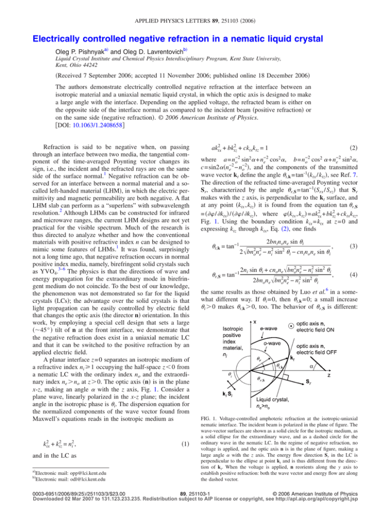
APPLIED PHYSICS LETTERS 89, 251103 共2006兲 Electrically controlled negative refraction in a nematic liquid crystal Oleg P. Pishnyaka兲 and Oleg D. Lavrentovichb兲 Liquid Crystal Institute and Chemical Physics Interdisciplinary Program, Kent State University, Kent, Ohio 44242 共Received 7 September 2006; accepted 11 November 2006; published online 18 December 2006兲 The authors demonstrate electrically controlled negative refraction at the interface between an isotropic material and a uniaxial nematic liquid crystal, in which the optic axis is designed to make a large angle with the interface. Depending on the applied voltage, the refracted beam is either on the opposite side of the interface normal as compared to the incident beam 共positive refraction兲 or on the same side 共negative refraction兲. © 2006 American Institute of Physics. 关DOI: 10.1063/1.2408658兴 Refraction is said to be negative when, on passing through an interface between two media, the tangential component of the time-averaged Poynting vector changes its sign, i.e., the incident and the refracted rays are on the same side of the surface normal.1 Negative refraction can be observed for an interface between a normal material and a socalled left-handed material 共LHM兲, in which the electric permittivity and magnetic permeability are both negative. A flat LHM slab can perform as a “superlens” with subwavelength resolution.2 Although LHMs can be constructed for infrared and microwave ranges, the current LHM designs are not yet practical for the visible spectrum. Much of the research is thus directed to analyze whether and how the conventional materials with positive refractive index n can be designed to mimic some features of LHMs.1 It was found, surprisingly not a long time ago, that negative refraction occurs in normal positive index media, namely, birefringent solid crystals such as YVO4.3–6 The physics is that the directions of wave and energy propagation for the extraordinary mode in birefringent medium do not coincide. To the best of our knowledge, the phenomenon was not demonstrated so far for the liquid crystals 共LCs兲; the advantage over the solid crystals is that light propagation can be easily controlled by electric field that changes the optic axis 共the director n兲 orientation. In this work, by employing a special cell design that sets a large 共⬃45° 兲 tilt of n at the front interface, we demonstrate that the negative refraction does exist in a uniaxial nematic LC and that it can be switched to the positive refraction by an applied electric field. A planar interface z = 0 separates an isotropic medium of a refractive index ni 艌 1 occupying the half-space z ⬍ 0 from a nematic LC with the ordinary index no and the extraordinary index ne ⬎ no at z ⬎ 0. The optic axis 共n兲 is in the plane x-z, making an angle ␣ with the z axis, Fig. 1. Consider a plane wave, linearly polarized in the x-z plane; the incident angle in the isotropic phase is i. The dispersion equation for the normalized components of the wave vector found from Maxwell’s equations reads in the isotropic medium as k2ix + kiz2 = n2i , and in the LC as a兲 Electronic mail: opp@lci.kent.edu Electronic mail: odl@lci.kent.edu b兲 共1兲 共2兲 ak2tx + bktz2 + cktxktz = 1 −2 −2 2 2 2 2 b = n−2 where a = n−2 o sin ␣ + ne cos ␣, o cos ␣ + ne sin ␣, −2 −2 c = sin2␣共ne − no 兲, and the components of the transmitted wave vector kt define the angle t,k = tan-1共ktx / ktz兲, see Ref. 7. The direction of the refracted time-averaged Poynting vector Sr, characterized by the angle r,S = tan−1共Srx / Srz兲 that Sr makes with the z axis, is perpendicular to the kt surface, and at any point 共ktx , ktz兲 it is found from the equation tan r,S = 共 / ktx兲 / 共 / ktz兲, where 共ktx , ktz兲 = ak2tx + bktz2 + cktxktz, Fig. 1. Using the boundary condition kix = ktx at z = 0 and expressing ktz through ktx, Eq. 共2兲, one finds t,k = tan−1 r,S = tan−1 2bninone sin i , 2冑bn2on2e − n2i sin2 i − cninone sin i 2ni sin i + cnone冑bn2on2e − n2i sin2 i 2bnone冑bn2on2e − n2i sin2 i , 共3兲 共4兲 the same results as those obtained by Luo et al.6 in a somewhat different way. If i = 0, then t,k = 0; a small increase i ⬎ 0 makes t,k ⬎ 0, too. The behavior of r,S is different: FIG. 1. Voltage-controlled amphoteric refraction at the isotropic-uniaxial nematic interface. The incident beam is polarized in the plane of figure. The wave-vector surfaces are shown as a solid circle for the isotropic medium, as a solid ellipse for the extraordinary wave, and as a dashed circle for the ordinary wave in the nematic LC. In the regime of negative refraction, no voltage is applied, and the optic axis n is in the plane of figure, making a large angle ␣ with the z axis. The energy flow direction Sr in the LC is perpendicular to the ellipse at point kt and is thus different from the direction of kt. When the voltage is applied, n reorients along the y axis to establish positive refraction: both the wave vector and energy flow are along the dashed vector. 0003-6951/2006/89共25兲/251103/3/$23.00 89, 251103-1 © 2006 American Institute of Physics Downloaded 02 Mar 2007 to 131.123.233.235. Redistribution subject to AIP license or copyright, see http://apl.aip.org/apl/copyright.jsp 251103-2 Appl. Phys. Lett. 89, 251103 共2006兲 O. P. Pishnyak and O. D. Lavrentovich FIG. 2. 共Color online兲 Theoretical and experimental data for the electrically controlled amphoteric refraction in E7. The extraordinary regime dependency r,S共i兲, Eq. 共4兲, is shown by the solid line and the ordinary regime dependency r共i兲, Eq. 共5兲, by the dashed line. In the extraordinary case, U = 0; negative refraction is observed for 0 ° ⬍ i ⬍ 12.5°. In the ordinary case, U = 5 V 共at 1 kHz兲. for i = 0, it can be negative, provided ␣ ⫽ 0 , / 2, as r,S共i = 0兲 = −tan−1关共n2e − n2o兲sin ␣ cos ␣ / 共n2o sin2 ␣ + n2e cos2 ␣兲兴. The solid line in Fig. 2 shows the dependence r,S共i兲 as calculated from Eq. 共4兲 with ni = 1, ␣ = 45°, and no = 1.52 and ne = 1.74 共both at 633 nm兲, characteristic of the nematic mixture E7 共EM Industries兲 used in our experiments. As clear from Fig. 2 and Eq. 共4兲, there is a range of the incident angles, 0 ⬍ i ⬍ ic, where ic ⬇ 12.5°, for which refraction is negative. The maximum 共negative兲 angle of refraction max r,S = −tan−1关共n2e − n2o兲 / 2none兴 = −7.7° is achieved when i = 0 and ␣ = tan−1共ne / no兲 ⬇ 49°. When n is turned parallel to the y axis, Fig. 1, the regime is ordinary. The wave vector and the ray vector would propagate at the same angle r共i兲 defined from ni sin i = no sin r , 共5兲 Fig. 2 共the dashed line兲. Therefore, by applying the electric field to the LC cell and reorienting n, one can switch between negative and positive refractions. The experimental setup is shown in Fig. 3. The He–Ne laser beam 共 = 633 nm兲 passes through a polarizer P to achieve linear polarization in the x-z plane and is focused by a 10⫻ microscope objective O to couple it into the middle of a cell filled with E7. The diameter of the focused spot is ⬃10 m so that the beam intensity is ⬃5 W / cm2. This intensity is well below the one that causes significant optically induced torques on n in the generation of the solitonlike formations, the so-called nematicons.8,9 FIG. 4. 共Color online兲 Photographs of voltage-controlled amphoteric refraction of a laser beam linearly polarized in the plane of figure, on passing through air into the entry glass plate, i ⬇ 5.5°, and then into the LC. At zero voltage, refraction is negative, r,S ⬇ −4.2° 共a兲; at U = 5 V, it switches into the positive one, r ⬇ 3.8° 共b兲. Propagation of the beam is monitored using a chargecoupled device camera facing the x-z plane of the cell through a microscope objective. The LC cell of thickness d = 90 m is assembled using two glass substrates with conductive indium tin oxide layers. The substrates are coated with a polyimide PI2555 共Microsystems兲 film rubbed to align n uniformly parallel to the x-z plane but under the angle ␣ = 共45± 1兲°, to the z axis 共Fig. 1兲. The third glass plate of crucial importance was an entry glass plate perpendicular to the first two. This plate imposes a highly tilted, ␣ = 共45± 5兲°, orientation of n at the entry interface 关achieved by an obliquely deposited layer of SiOx 共Ref. 10兲兴, thus simultaneously preserving the uniformity of n throughout the entire cell, Fig. 3. The LC cell can be rotated around the y axis to control i. The experimental data r,S共i兲 and r共i兲 are in good agreement with the behavior predicted by Eqs. 共4兲 and 共5兲, respectively, Fig. 2. Negative refraction occurs for a wide range of the incident angles, 0 ⬍ i ⬍ 12.5°, when there is no field, Figs. 2 and 4共a兲. The maximum 共negative兲 bend angle is r,S ⬇ −8°, as in the theory. By applying the electric field and reorienting n along the y axis, one switches negative refraction to positive one, Figs. 2 and 4共b兲. We deliberately used low voltages 共U = 5 V兲 to demonstrate the efficiency of the control; for d = 90 m and U = 5 V, the angle between n and the y axis is less than 2° within the central portion 共of width ⬇25 m兲 of the LC cell, as established by numerical simulations of the dielectric response of E7. Some deviations of the experimental r共i兲 from Eq. 共5兲, noticeable at large i, Fig. 2, are caused by the finite width of the region with realigned n; as the beam gets defocused in the LC, it propagates in the regions where n deviates from the y axis. Of course, a higher voltage would reorient a larger portion of the nematic cell and thus would refine the ordinary regime, as observed. To conclude, we used one of the simplest possible geometries to prove the very existence of negative refraction and electrically controlled amphoteric refraction in LCs that can be used in a variety of applications, e.g., beam steering. In our cells with a large d, the characteristic time of director reorientation was tens of seconds. However, there is no principal obstacle to speed the response up by reducing d, by using dual-frequency materials or higher voltages. The biggest advantage of LCs is in the flexibility and controllability FIG. 3. 共Color online兲 Experimental setup. The SiOx coated glass plate is the entry plate for the laser beam. At zero voltage, the director n is in the x-z plane. The electric field E serves to reorient n along the y axis. Downloaded 02 Mar 2007 to 131.123.233.235. Redistribution subject to AIP license or copyright, see http://apl.aip.org/apl/copyright.jsp 251103-3 Appl. Phys. Lett. 89, 251103 共2006兲 O. P. Pishnyak and O. D. Lavrentovich of the optical axis n. Even higher degree of flexibility is expected when the LC is used as one of the components in heterogeneous materials, in which one might hope to expand beyond the regime of negative refraction in the positive index anisotropic material presented in this work. One of the authors 共O.D.L.兲 thanks N. Kotov, E. E. Narimanov, V. M. Shalaev and P. Palffy-Muhoray for stimulating discussions about negative index materials. The authors thank A. Golovin for the help in experiments. The work was partially supported by NSF DMR 0504516 and MURI 共AFOSR兲 grant FA9550-06-1-0337 on negative index materials. Y. Zhang and A. Mascarenhas, Mod. Phys. Lett. B 19, 21 共2005兲. J. B. Pendry, Contemp. Phys. 45, 191 共2004兲. 3 Y. Zhang, B. Fluegel, and A. Mascarenhas, Phys. Rev. Lett. 91, 157404 共2003兲. 4 Z. Liu, Z. Lin, and S. T. Chui, Phys. Rev. B 69, 115402 共2004兲. 5 X. L. Chen, M. He, Y. X. Du, W. Y. Wang, and D. F. Zhang, Phys. Rev. B 72, 113111 共2005兲. 6 H. Luo, W. Hu, X. Yi, H. Liu, and J. Zhu, Opt. Commun. 254, 353 共2005兲. 7 G. R. Fowles, Introduction to Modern Optics, 2nd ed. 共Dover, New York, 1989兲, p. 328. 8 J. Beeckman, K. Neyts, X. Hutsebaut, C. Cambournac, and M. Haelterman, Opt. Quantum Electron. 37, 95 共2005兲. 9 A. Alberucci, M. Peccianti, G. Assanto, G. Coschignano, A. De Luca, and C. Umeton, Opt. Lett. 30, 1381 共2005兲. 10 A. B. Golovin, S. V. Shiyanovskii, and O. D. Lavrentovich, Appl. Phys. Lett. 83, 3864 共2003兲. 1 2 Downloaded 02 Mar 2007 to 131.123.233.235. Redistribution subject to AIP license or copyright, see http://apl.aip.org/apl/copyright.jsp
