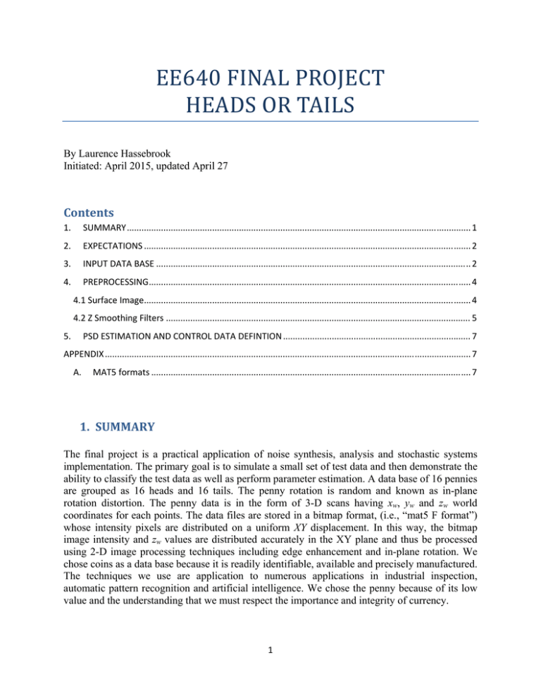
EE640 FINAL PROJECT HEADS OR TAILS Contents
advertisement

EE640FINALPROJECT HEADSORTAILS By Laurence Hassebrook Initiated: April 2015, updated April 27 Contents 1. SUMMARY ............................................................................................................................................. 1 2. EXPECTATIONS ...................................................................................................................................... 2 3. INPUT DATA BASE ................................................................................................................................. 2 4. PREPROCESSING .................................................................................................................................... 4 4.1 Surface Image ...................................................................................................................................... 4 4.2 Z Smoothing Filters ............................................................................................................................. 5 5. PSD ESTIMATION AND CONTROL DATA DEFINTION ............................................................................. 7 APPENDIX ...................................................................................................................................................... 7 A. MAT5 formats ................................................................................................................................... 7 1. SUMMARY The final project is a practical application of noise synthesis, analysis and stochastic systems implementation. The primary goal is to simulate a small set of test data and then demonstrate the ability to classify the test data as well as perform parameter estimation. A data base of 16 pennies are grouped as 16 heads and 16 tails. The penny rotation is random and known as in-plane rotation distortion. The penny data is in the form of 3-D scans having xw, yw and zw world coordinates for each points. The data files are stored in a bitmap format, (i.e., “mat5 F format”) whose intensity pixels are distributed on a uniform XY displacement. In this way, the bitmap image intensity and zw values are distributed accurately in the XY plane and thus be processed using 2-D image processing techniques including edge enhancement and in-plane rotation. We chose coins as a data base because it is readily identifiable, available and precisely manufactured. The techniques we use are application to numerous applications in industrial inspection, automatic pattern recognition and artificial intelligence. We chose the penny because of its low value and the understanding that we must respect the importance and integrity of currency. 1 The random variable within the data is the rotation angle and the random process is the surface noise. There is also some feature variation between coins. When we test the data we will be evaluating our ability to discriminate between heads and tails as well as estimating the rotation angle of the test data. We will first select a single head and a single tail scan to be used to develop our classifiers and angle estimators. From these two coin scans, we will select a preprocessing algorithm that tends to orthogonalize the data. From that we will estimate the PSDs of the coins. Using white Gaussian noise images and a filter based on the PSD results, we synthesize a “training set” of control images representing the rotation distortion and the PSD of the heads and tails data. Using the training set synthesis, we determine the maximum angle between adjacent rotations which in turn determines the minimum size of the training set. Given the training set correlation matrix, we form a filter bank based on the correlation matrix. From that we form a maximum likelihood ration based filter bank for discriminating between heads and tails based on the Rayleigh quotient. After classification we use the associated filters to estimate the rotation angle. 2. EXPECTATIONS The students are expected to turn in a single report per group. Each section starts with a definition of what the student needs to show or implement. This may include mathematical derivation and/or MATLAB implementation. The student will be provided with existing MATLAB code to minimize development of software not directly related to the study of stochastic systems. 3. INPUTDATABASE The student should select one mat5 data set for heads and one for tails to represent that particular class. The data was scanned using the multi-frequency Phase Measuring Profilometry (PMP) [1] method. The format of the data is in MAT5 format [2] described in Appendix A. Use PreviewDataSet.m to preview the data set. There are several controls in PreviewDataSet.m: Targetselect: Index of selected target which varies between 0 and (N-1) TurnOnImage: 0 for original images, 1 for median normalized gain and 2 for surface normal. TurnOnEdge: 0 for Z depth, 1 for Sobel with clipping threshold, and 2 for Moving Least Squares filter. SobelClip: The Sobel edge enhancement clips result based on SobelClip times Sobel peak. So any values greater than SobelClip are set to the value of SobelClip. TurnOnZSmoothing: 0 for no smoothing of Z coordinates, 1 for smoothing Z using filter. FilterType: Smoothing filter type. 0 for none, 1 for Moving Average Rectangle and 2 for Gaussian. MAfilter: Width of MA filter and should be an odd number to be symmetric. GausfilterSTD: Gaussian filter parameter which controls shape width. 2 two controls, and which control if the images are original, metallic, depth, sobel edgehance Z and Moving Least Square Filtering. Figure 1: Data set of penny heads with TurnOnImage=0. 3 Figure 2: Data set of penny tails, C matrix, with TurnOnImage=0. 4. PREPROCESSING The data is pre-processed before viewing and usage. The student should indicate and show their enhanced images selected as the training images for the target (i.e., heads) and clutter (i.e., tails) classes. Indicate what filtering parameters are used and which enhancement methods are used. 4.1SurfaceImage For viewing, the C matrix can be used in original form (TurnOnImage=0) or median normalized (TurnOnImage=1). Both options for both heads and tails of mat5 C matrix 0, are shown in Fig. 3. For the median normalization, we select all pixels for I > ithresh and find the median value. All pixels are scaled such that the median value is 128. The image is clipped to be between 0 and 255. 4 Figure 3: Image C of mat5 index 0. (top, left) Original heads image. (bottom, left) Median normalized head. (top, right) Original tail. (bottom, right) Median normalized tail. 4.2ZSmoothingFilters The input Z data can be smoothed with two types of linear filters. By controlling the filter parameter, the smoothing of the Z surface can improve the results of the edge enhancement processes. In the mathematical equations we ignore the circular wrap that the finite image space requires. In implementation, the origin is in the corner and is then wrapped around. For FilterType=1, a Moving Average (MA) filter is convolved with the Z data matrix. The MA filter is a Ma x Ma rectangular filter where Ma = MAfilter. The MA filter is defined as m n rect rect Ma M a hm, n M a2 and is convolved with the input Z matrix such that Z s m, n Z m, n hm, n . For FilterType=2, a Gaussian filter is convolved with the Z data matrix. 5 hm, n 2 2 1 exp1 m n 2 2 E where E is E M y 1 N x 1 hm, n m 0 n 0 Preview data offers two types of edge enhancement, Sobel edge enhancement and a differencing Moving Least Squares filter. Both enhancement methods tend to orthogonalize the data which should improve discrimination performance. Both are also sensitive to noise which are affected by the smoothing process. The trade off in smoothing is too much will blur the features needed for discrimination versus allowing surface noise that reduces performance. Results for both methods and both classes are shown in Fig. 4. Figure 4: (left column) Target image. (right column) Clutter image. (Top row) Sobel edge enhancement. (Bottom row) MLS filtering. 6 5. PSDESTIMATIONANDCONTROLDATADEFINTION Based on the selected target and clutter preprocessed images, we synthesize control data to be colored stationary noise having the same PSD as the target and clutter classes, respectively. RANDOM INPLANE ROTATION AND THE CORRELATION MATRIX COMPOSITE CORRELATION FILTER BANK DETECTION AND DISCRIMINATION ROTATION ANGLE ESTIMATION REFERENCES 1. Jie-lin Li, L.G. Hassebrook and Chun Guan, “Optimized Two-Frequency Phase-Measuring-Profilometry Light-Sensor Temporal-Noise Sensitivity,” JOSA A, 20(1), 106-115, (2003). 2. MAT5 format description: http://www.engr.uky.edu/~lgh/soft/softmat5format.htm 3. W. J. Chimitt and L.G. Hassebrook, “Scene reconstruction from partially overlapping images with use of composite filters,” JOSA A, 16(9), 2124-2135, September (1999). 4. L. G. Hassebrook, B.V.K. Vijaya Kumar and L. Hostetler, "Linear Phase Coefficient Composite Filter Banks for Distortion-Invariant Optical Pattern Recognition," Optical Engineering, 29, 1033-1043, (Sept. 1990). 5. L. G. Hassebrook, M. E. Lhamon, M. Wang and J. Chatterjee, "Postprocessing of Correlation for Orientation Estimation," Optical Engineering, 36(10), 2710-2718, October, (1997). APPENDIX A. MAT5formats The mat5 format consists of 5 matrices embedded into a single 32 bit Bitmap file. The mat5 image is My rows by Nx columns. The matrices are a color matrix C, an indicator matrix I, X world coordinate matrix X, Y world coordinate matrix Y and Z world coordinate matrix Z. Matrix C I X Y Z Dimensions My x Nx x 3 My x Nx My x Nx My x Nx My x Nx Element format 3 bytes representing RGB 1 byte representing quality 4 byte float representing X world coordinates 4 byte float representing Y world coordinates 4 byte float representing Z world coordinates Given a threshold “ithresh” the valid elements are where I(m,n) >=ithresh where I(m,n) varies between 0 and 255. 7


