Component Protection How To Use Current-Limitation Charts
advertisement
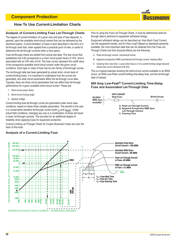
Component Protection How To Use Current-Limitation Charts Prior to using the Fuse Let-Through Charts, it must be determined what letthrough data is pertinent to equipment withstand ratings. Equipment withstand ratings can be described as: How Much Fault Current can the equipment handle, and for How Long? Based on standards presently available, the most important data that can be obtained from the Fuse LetThrough Charts and their physical effects are the following: Analysis of Current-Limiting Fuse Let-Through Charts The degree of current-limitation of a given size and type of fuse depends, in general, upon the available short-circuit current that can be delivered by the electrical system. Current-limitation of fuses is best described in the form of a let-through chart that, when applied from a practical point of view, is useful to determine the let-through currents when a fuse opens. Fuse let-through charts are plotted from actual test data. The test circuit that establishes line A-B corresponds to a short circuit power factor of 15%, that is associated with an X/R ratio of 6.6. The fuse curves represent the cutoff value of the prospective available short-circuit current under the given circuit conditions. Each type or class of fuse has its own family of let-through curves. The let-through data has been generated by actual short- circuit tests of current-limiting fuses. It is important to understand how the curves are generated, and what circuit parameters affect the let-through curve data. Typically, there are three circuit parameters that can affect fuse let-through performance for a given available short-circuit current. These are: A. Peak let-through current: mechanical forces B. Apparent prospective RMS symmetrical let-through current: heating effect C. Clearing time: less than 1⁄2 cycle when fuse is in it’s current-limiting range (beyond where fuse curve intersects A-B line). This is a typical example showing the short-circuit current available to an 800A circuit, an 800A Low-Peak current-limiting time-delay fuse, and the let-through data of interest. 800 Amp Low-Peak® Current-Limiting Time-Delay Fuse and Associated Let-Through Data 1. Short-circuit power factor 2. Short-circuit closing angle 3. Applied voltage Current-limiting fuse let-through curves are generated under worst case conditions, based on these three variable parameters. The benefit to the user is a conservative resultant let-through current (both Ip and IRMS). Under actual field conditions, changing any one or a combination of these will result in lower let-through currents. This provides for an additional degree of reliability when applying fuses for equipment protection. Current-Limiting Let-Through Charts for Cooper Bussmann fuses are near the back of this book. B 400,000 300,000 Available Peak ShortCircuit Current = 198,000A I 200,000 Available RMS ShortCircuit Current = 86,000A 100,000 80,000 60,000 Peak Let-Through Current of Fuse= 49,000A 800A RMS Let-Through Current of Fuse = 21,000A 30,000 20,000 tm 10,000 8000 6000 TIME ta tc tm = Fuse Melt Time ta = Fuse Arc Time tc = Fuse Clearing Time AMP RATING 4000 3000 A 200,000 100,000 60,000 80,000 30,000 40,000 20,000 6000 4000 3000 2000 1000 8000 10,000 2000 1000 INSTANTANEOUS PEAK LET-THROUGH CURRENT IN AMPS Analysis of a Current-Limiting Fuse PROSPECTIVE SHORT-CIRCUIT CURRENT – SYMMETRICAL RMS AMPS 68 ©2005 Cooper Bussmann Component Protection How To Use Current-Limitation Charts How to Use the Let-Through Charts Using the example given, one can determine the pertinent let-through data for the KRP-C-800SP amp Low-Peak fuse. The Let-Through Chart pertaining to the 800A Low-Peak fuse is illustrated. A. Determine the PEAK let-through CURRENT. Step 1. Enter the chart on the Prospective Short-Circuit current scale at 86,000 amps and proceed vertically until the 800A fuse curve is intersected. Follow horizontally until the Instantaneous Peak Let-Through Current scale is intersected. Read the PEAK let-through CURRENT as 49,000A. (If a fuse had not been used, the peak current would have been 198,000A.) Step 2. Step 3. Most electrical equipment has a withstand rating that is defined in terms of an RMS symmetrical-short-circuit current, and in some cases, peak let-through current. These values have been established through short circuit testing of that equipment according to an accepted industry standard. Or, as is the case with conductors, the withstand rating is based on a mathematical calculation and is also expressed in an RMS short-circuit current. If both the let-through currents (IRMS and Ip) of the current-limiting fuse and the time it takes to clear the fault are less than the withstand rating of the electrical component, then that component will be protected from short circuit damage. The following Table shows typical assumed short-circuit current ratings for various unmarked components. B. Determine the APPARENT PROSPECTIVE RMS SYMMETRICAL let-through CURRENT. Typical Short-Circuit Current Ratings For Unmarked Components* Step 1. Enter the chart on the Prospective Short-Circuit current scale at 86,000A and proceed vertically until the 800A fuse curve is intersected. Follow horizontally until line A-B is intersected. Proceed vertically down to the Prospective Short-Circuit Current. Read the APPARENT PROSPECTIVE RMS SYMMETRICAL let-through CURRENT as 21,000A. (The RMS SYMMETRICAL let-through CURRENT would be 86,000A if there were no fuse in the circuit.) Component Step 2. Step 3. Step 4. Current-Limitation Curves — Cooper Bussmann Low-Peak Time-Delay Fuse KRP-C-800SP Short- Circuit Rating, kA Industrial Control Equipment: a. Auxiliary Devices b. Switches (other than Mercury Tube Type) c. Mercury Tube Switches Rated over 60 amperes or over 250 volts Rated 250 volts or less, 60 amperes or less, and over 2kVA Rated 250 volts or less and 2kVA or less Meter Socket Base Photoelectric Switches Receptacle (GFCI Type) Receptacle (other than GFCI Type) Snap Switch Terminal Block Thermostat 5 5 5 3.5 1 10 5 10 2 5 10 5 *Based upon information in UL 891 (Dead-Front Switchboards) The following components will be analyzed by establishing the short-circuit withstand data of each component and then selecting the proper currentlimiting fuses for protection: • Wire and Cable • Bus (Busway, Switchboards, Motor Control Centers and Panelboards) • Transfer Switches • HVAC Equipment • Ballasts • Circuit Breakers A detailed analysis of motor circuit component protection is provided later in the section on motor circuits. C. Clearing time If the RMS Symmetrical available is greater than the point where the fuse characteristic curve intersects with the diagonal A-B line, then the fuse clearing time is 1⁄2 cycle or less. In this example, the intersection is approximately 9500A; so for short-circuit currents above approximately 9500A, this KRP-C-800SP fuse is current-limiting. The current-limiting charts and tables for Cooper Bussmann fuses are in the rear of this book under “Current-Limiting Let-Through Charts.” Refer to these tables when analyzing component protection in the following sections. ©2005 Cooper Bussmann 69 Cooper Bussmann Current-Limiting Fuse Let-Through Data See pages 67 to 69 for current-limiting definition and how to analyze these charts. Low-Peak Class L Time-Delay Fuses KRP-C_SP KRP-C_SP Fuse – RMS Let-Through Currents (kA) 1000000 900000 800000 700000 600000 Prosp. Short C.C. B 500000 400000 6000A 5000A 4000A 3000A 200000 2500A 2000A 1600A 1200A 601 800 1200 1600 2000 2500 3000 4000 5000 6000 IRMS IRMS IRMS IRMS IRMS IRMS IRMS IRMS IRMS IRMS 5,000 5 5 5 5 5 5 5 5 5 5 10,000 8 10 10 10 10 10 10 10 10 10 15,000 9 12 15 15 15 15 15 15 15 15 13 17 20 20 20 20 20 20 20 20,000 10 25,000 11 14 19 22 25 25 25 25 25 25 30,000 11 14 20 24 27 30 30 30 30 30 35,000 12 15 21 25 29 35 35 35 35 35 40,000 13 16 22 26 30 35 40 40 40 40 50,000 14 17 23 28 32 37 50 50 50 50 60,000 15 18 25 30 34 40 49 60 60 60 70,000 15 19 26 32 36 42 52 62 70 70 10000 9000 8000 7000 6000 80,000 16 20 27 33 38 44 54 65 76 80 90,000 17 21 29 34 39 45 56 67 79 90 5000 100,000 17 22 30 36 41 47 58 70 81 100 3000 150,000 20 25 34 41 47 54 67 80 93 104 A 200,000 22 27 37 45 51 59 73 87 102 114 250,000 24 29 40 49 55 64 79 94 110 123 300,000 25 31 43 52 59 68 84 100 117 30 100000 90000 80000 70000 60000 800A 601A 50000 40000 AMPERE RATING INSTANTANEOUS PEAK LET THRU CURRENT IN AMPERES 300000 Fuse Size 30000 20000 4000 2000 300000 200000 60000 70000 80000 90000 100000 50000 40000 30000 20000 5000 6000 7000 8000 9000 10000 4000 3000 2000 1000 1000 Note: For IRMS value at 300,000 amperes, consult Factory. PROSPECTIVE SHORT CIRCUIT CURRENT - SYMMETRICAL RMS AMPERES Low-Peak Class J, Dual-Element Time-Delay Fuses LPJ_SP LPJ_SP Fuse – RMS Let-Through Currents (kA) 15 30 60 100 200 400 600 IRMS IRMS IRMS IRMS IRMS IRMS IRMS 400A 1,000 1 1 1 1 1 1 1 200A 3,000 1 1 1 2 2 3 3 100A 5,000 1 1 1 2 3 5 5 60A 10,000 1 1 2 2 4 6 8 30A 15,000 1 1 2 3 4 7 9 15A 20,000 1 1 2 3 4 7 10 25,000 1 1 2 3 5 8 10 30,000 1 1 2 3 5 8 11 35,000 1 1 2 4 5 9 12 40,000 1 2 3 4 6 9 12 50,000 1 2 3 4 6 10 13 60,000 1 2 3 4 6 11 14 80,000 1 2 3 5 7 12 15 100,000 1 2 4 5 8 12 17 150,000 1 2 4 6 9 14 19 200,000 2 3 4 6 9 16 21 250,000 2 3 5 7 10 17 23 300,000 2 3 5 7 11 18 24 600A 50000 40000 10000 9000 8000 7000 6000 5000 4000 3000 AMPERE RATING INSTANTANEOUS PEAK LET-THROUGH CURRENT IN AMPERES 30000 20000 2000 1000 900 800 700 600 500 400 300 A 200 PROSPECTIVE SHORT-CIRCUIT CURRENT - SYMMETRICAL RMS AMPERES 300000 200000 60000 70000 80000 90000 100000 50000 40000 30000 20000 6000 7000 8000 9000 10000 4000 5000 3000 2000 600 700 800 900 1000 500 400 300 200 100 100 Fuse Size Prosp. Short C.C. B 100000 90000 80000 70000 60000 Note: For IRMS value at 300,000 amperes, consult Factory. 210 ©2005 Cooper Bussmann Cooper Bussmann Current-Limiting Fuse Let-Through Data See pages 67 to 69 for current-limiting definition and how to analyze these charts. Low-Peak Class RK1 Dual-Element Time-Delay Fuses LPN-RK_SP LPN-RK_SP – RMS Let-Through Currents (kA) Prosp. Short C.C. B Fuse Size 30 60 100 200 400 600 IRMS IRMS IRMS IRMS IRMS IRMS 1,000 1 1 1 1 1 1 2,000 1 1 2 2 2 2 3,000 1 1 2 3 3 3 5,000 1 2 2 3 5 5 10,000 1 2 3 4 7 9 15,000 1 2 3 5 8 11 20,000 1 3 3 5 8 11 25,000 1 3 3 5 9 12 30,000 2 3 4 6 9 12 35,000 2 3 4 6 10 13 40,000 2 3 4 6 10 13 50,000 2 3 4 7 11 14 4,000 60,000 2 3 4 7 11 16 3,000 70,000 2 3 4 7 12 16 80,000 2 4 5 8 12 16 90,000 2 4 5 7 13 17 100,000 2 4 5 8 13 17 150,000 2 4 6 9 15 19 200,000 3 5 6 11 16 20 250,000 3 5 7 11 17 21 300,000 3 6 7 12 18 22 600 400,000 300,000 AMPERE RATING INSTANTANEOUS PEAK LET-THROUGH CURRENT IN AMPERES 200,000 100,000 90,000 80,000 70,000 60,000 50,000 600A 40,000 400A 30,000 200A 20,000 100A 60A 10,000 9,000 8,000 7,000 6,000 30A 5,000 A 2,000 300,000 200,000 80,000 100,000 60,000 40,000 30,000 20,000 8,000 10,000 6,000 4,000 3,000 2,000 1,000 1,000 PROSPECTIVE SHORT-CIRCUIT CURRENT - SYMMETRICAL RMS AMPERES Low-Peak Class RK1 Dual-Element Time-Delay Fuses LPS-RK_SP LPS-RK_SP – RMS Let-Through Currents (kA) Prosp. Short C.C. Fuse Size 30 60 100 200 400 IRMS IRMS IRMS IRMS IRMS IRMS 1,000 1 1 1 1 1 1 2,000 1 1 2 2 2 2 AMPERE RATING B 3,000 1 1 2 3 3 3 5,000 1 2 2 3 5 5 600A 10,000 1 2 3 4 7 10 400A 15,000 1 2 3 5 8 11 200A 20,000 2 3 3 5 9 12 25,000 2 3 4 6 9 12 30,000 2 3 4 6 10 13 35,000 2 3 4 6 10 13 40,000 2 3 4 6 10 14 50,000 2 3 5 7 11 15 4,000 60,000 2 4 5 7 12 15 3,000 70,000 2 4 5 8 13 16 80,000 2 4 5 8 13 16 90,000 2 4 5 8 13 17 100,000 2 4 6 9 14 17 150,000 3 5 6 10 15 19 200,000 3 5 7 11 16 21 250,000 3 6 7 12 17 22 300,000 3 6 7 12 18 23 400,000 300,000 INSTANTANEOUS PEAK LET-THROUGH CURRENT IN AMPERES 200,000 100,000 90,000 80,000 70,000 60,000 50,000 40,000 30,000 20,000 100A 60A 10,000 9,000 8,000 7,000 6,000 30A 5,000 A 2,000 200,000 300,000 100,000 80,000 60,000 40,000 30,000 20,000 10,000 8,000 6,000 4,000 3,000 2,000 1,000 1,000 PROSPECTIVE SHORT-CIRCUIT CURRENT - SYMMETRICAL RMS AMPERES ©2005 Cooper Bussmann 211 Cooper Bussmann Current-Limiting Fuse Let-Through Data See pages 67 to 69 for current-limiting definition and how to analyze these charts. Fusetron Class RK5 Dual-Element Time-Delay Fuses FRN-R 300000 Prosp. Short C.C. 200000 100000 90000 80000 70000 60000 50000 30 60 100 200 400 600 IRMS IRMS IRMS IRMS IRMS IRMS 5,000 1 2 3 5 5 5 10,000 2 3 4 7 10 10 15,000 2 3 5 8 11 15 600A 20,000 2 4 5 8 12 16 25,000 2 4 6 9 13 17 30,000 2 4 6 10 14 18 100A 35,000 2 4 6 10 15 19 60A 40,000 2 5 7 11 15 20 50,000 3 5 7 11 17 21 60,000 3 5 8 12 18 22 70,000 3 6 8 13 19 23 80,000 3 6 8 13 19 24 90,000 3 6 9 14 20 25 100,000 3 6 9 14 21 26 150,000 4 7 10 16 24 29 200,000 4 8 11 18 26 32 400A 200A 40000 30000 Fuse Size AMPERE RATING B 400000 INSTANTANEOUS PEAK LET-THROUGH CURRENT IN AMPERES FRN-R – RMS Let-Through Currents (kA) 20000 10000 9000 8000 7000 6000 5000 30A 4000 3000 A 2000 200000 50000 60000 70000 80000 90000 100000 30000 40000 20000 4000 5000 6000 7000 8000 9000 10000 3000 2000 1000 1000 PROSPECTIVE SHORT-CIRCUIT CURRENT - SYMMETRICAL RMS AMPERES Fusetron Class RK5 Dual-Element Time-Delay Fuses FRS-R 30 60 100 200 400 600 IRMS IRMS IRMS IRMS IRMS IRMS 5,000 1 1 3 4 5 5 10,000 1 2 4 5 9 10 15,000 1 2 4 6 10 14 20,000 2 2 5 7 11 15 600A 25,000 2 2 5 7 12 17 400A 30,000 2 3 5 8 13 18 200A 35,000 2 3 5 8 13 18 40,000 2 3 6 9 14 19 50,000 2 3 6 9 14 20 60A 60,000 2 3 6 10 15 22 30A 70,000 3 4 7 11 17 23 80,000 3 4 7 12 17 23 90,000 3 4 7 12 17 24 100,000 3 4 8 13 18 25 150,000 3 5 9 14 21 27 200,000 4 6 9 16 23 32 300000 INSTANTANEOUS PEAK LET-THROUGH CURRENT IN AMPERES 200000 100000 90000 80000 70000 60000 50000 Fuse Size AMPERE RATING Prosp. Short C.C. B 400000 FRS-R – RMS Let-Through Currents (kA) 40000 30000 100A 20000 10000 9000 8000 7000 6000 5000 4000 3000 A 2000 200000 60000 70000 80000 90000 100000 50000 40000 30000 20000 6000 7000 8000 9000 10000 5000 4000 3000 2000 1000 1000 PROSPECTIVE SHORT-CIRCUIT CURRENT - SYMMETRICAL RMS AMPERES 212 ©2005 Cooper Bussmann Cooper Bussmann Current-Limiting Fuse Let-Through Data See pages 67 to 69 for current-limiting definition and how to analyze these charts. JJN – RMS Let-Through Current (kA) Prosp. Short C.C. B 30 60 100 200 400 600 800 IRMS IRMS IRMS IRMS IRMS IRMS IRMS IRMS IRMS 500 1 1 1 1 1 1 1 1 1 1,000 1 1 1 1 1 1 1 1 1 5,000 1 1 1 1 2 3 5 5 5 10,000 1 1 1 2 2 4 6 7 9 15,000 1 1 1 2 3 4 6 9 10 20,000 1 1 1 2 3 5 7 10 11 25,000 1 1 2 2 3 5 7 10 12 30,000 1 1 2 2 3 5 8 11 13 35,000 1 1 2 3 4 6 8 11 13 40,000 1 1 2 3 4 6 9 11 13 50,000 1 1 2 3 4 7 9 12 15 1,000 800 600 60,000 1 1 2 3 4 7 10 13 16 70,000 1 1 2 3 5 7 10 14 17 400 300 80,000 1 2 2 3 5 8 11 15 17 90,000 1 2 2 3 6 8 11 15 18 100,000 1 2 2 4 6 8 12 16 19 150,000 1 2 3 4 6 9 13 17 22 200,000 2 2 3 4 7 9 15 19 23 200,000 100,000 80,000 60,000 1200 800 600 40,000 30,000 400 200 100 20,000 10,000 8,000 6,000 60 30 15 4,000 3,000 2,000 200,000 60,000 80,000 100,000 30,000 40,000 20,000 6,000 8,000 10,000 3,000 4,000 2,000 600 800 1,000 300 400 200 200 100 A PROSPECTIVE SHORT-CIRCUIT CURRENT–SYMMETRICAL RMS AMPS Tron Class T Fast-Acting Fuses JJS 1200 JJS – RMS Let-Through Current (kA) B 400,000 300,000 AMPERE RATING INSTANTANEOUS PEAK LET-THROUGH CURRENT IN AMPS Fuse Size 15 400,000 300,000 AMPERE RATING INSTANTANEOUS PEAK LET-THROUGH CURRENT IN AMPS Tron Class T Fast-Acting Fuses JJN 200,000 100,000 80,000 60,000 40,000 30,000 60 100 200 400 600 IRMS IRMS IRMS IRMS IRMS IRMS 500 1 1 1 1 1 1 1 1 800 1 1 1 1 1 1 1 1 5,000 1 1 1 2 3 4 5 5 400 10,000 1 1 1 2 3 6 8 9 15,000 1 1 2 3 4 7 10 11 20,000 1 1 2 3 4 7 10 12 25,000 1 1 2 3 5 7 11 13 30,000 1 1 2 3 5 8 12 14 35,000 1 1 2 3 5 9 13 15 40,000 1 2 2 4 5 9 13 15 15 4,000 3,000 30 IRMS 1,000 100 60 30 10,000 8,000 6,000 15 IRMS 800 600 200 20,000 Fuse Size Prosp. Short C.C. 2,000 50,000 1 2 2 4 6 10 14 17 1,000 800 600 60,000 1 2 3 4 6 10 16 18 70,000 1 2 3 4 7 11 17 19 400 300 80,000 1 2 3 4 7 11 17 20 90,000 200,000 60,000 80,000 100,000 30,000 40,000 20,000 6,000 8,000 10,000 3,000 4,000 2,000 600 800 1,000 300 400 200 200 100 A PROSPECTIVE SHORT-CIRCUIT CURRENT–SYMMETRICAL RMS AMPS ©2005 Cooper Bussmann 1 2 3 4 7 12 18 21 100,000 2 2 3 5 7 12 19 22 150,000 2 3 4 6 8 14 22 25 200,000 2 3 4 6 9 16 24 28 213 Cooper Bussmann Current-Limiting Fuse Let-Through Data See pages 67 to 69 for current-limiting definition and how to analyze these charts. Low-Peak Class CC Time-Delay Fuses LP-CC LP-CC – RMS Let-Through Currents (A) INSTANTANEOUS PEAK LET-THROUGH CURRENT IN AMPS Prosp. Short C.C. Fuse Size 11/4 2 8/10 15 20 25 30 IRMS IRMS IRMS IRMS IRMS IRMS 1,000 100 135 240 305 380 435 3,000 140 210 350 440 575 580 5,000 165 255 420 570 690 710 10,000 210 340 540 700 870 1000 20,000 260 435 680 870 1090 1305 30,000 290 525 800 1030 1300 1520 40,000 315 610 870 1150 1390 1700 50,000 340 650 915 1215 1520 1820 60,000 350 735 1050 1300 1650 1980 80,000 390 785 1130 1500 1780 2180 100,000 420 830 1210 1600 2000 2400 200,000 525 1100 1600 2000 2520 3050 600 PROSPECTIVE SHORT-CIRCUIT CURRENT–SYMMETRICAL RMS AMPS Limitron Class J Fast-Acting Fuses JKS JKS – RMS Let-Through Currents (kA) 30 60 100 200 400 300,000 IRMS IRMS IRMS IRMS IRMS IRMS 200,000 5,000 1 1 2 3 4 5 10,000 1 2 3 4 6 9 15,000 1 2 3 4 7 10 20,000 1 2 3 5 8 11 600 25,000 2 3 3 6 9 12 400 30,000 2 3 3 6 9 13 200 35,000 2 3 4 6 9 13 40,000 2 3 4 7 10 14 50,000 2 3 4 7 10 15 60,000 2 3 5 7 11 16 70,000 2 3 5 8 11 17 80,000 2 3 5 8 12 17 90,000 2 4 6 9 13 18 100,000 2 4 6 9 13 18 150,000 2 5 6 9 14 22 200,000 3 5 7 10 16 24 AMPERE RATING 100,000 80,000 60,000 50,000 40,000 30,000 20,000 100 60 10,000 8,000 30 6,000 5,000 4,000 3,000 A 200,000 80,000 100,000 40,000 50,000 60,000 30,000 20,000 8,000 10,000 4,000 5,000 6,000 3,000 1,000 2,000 2,000 1,000 INSTANTANEOUS PEAK LET-THROUGH CURRENT IN AMPS Fuse Size Prosp. Short C.C. B 400,000 PROSPECTIVE SHORT-CIRCUIT CURRENT–SYMMETRICAL RMS AMPS 214 ©2005 Cooper Bussmann
