2.23 Hydrofoils & Propellers Exam #2 Friday April 27, 2007
advertisement
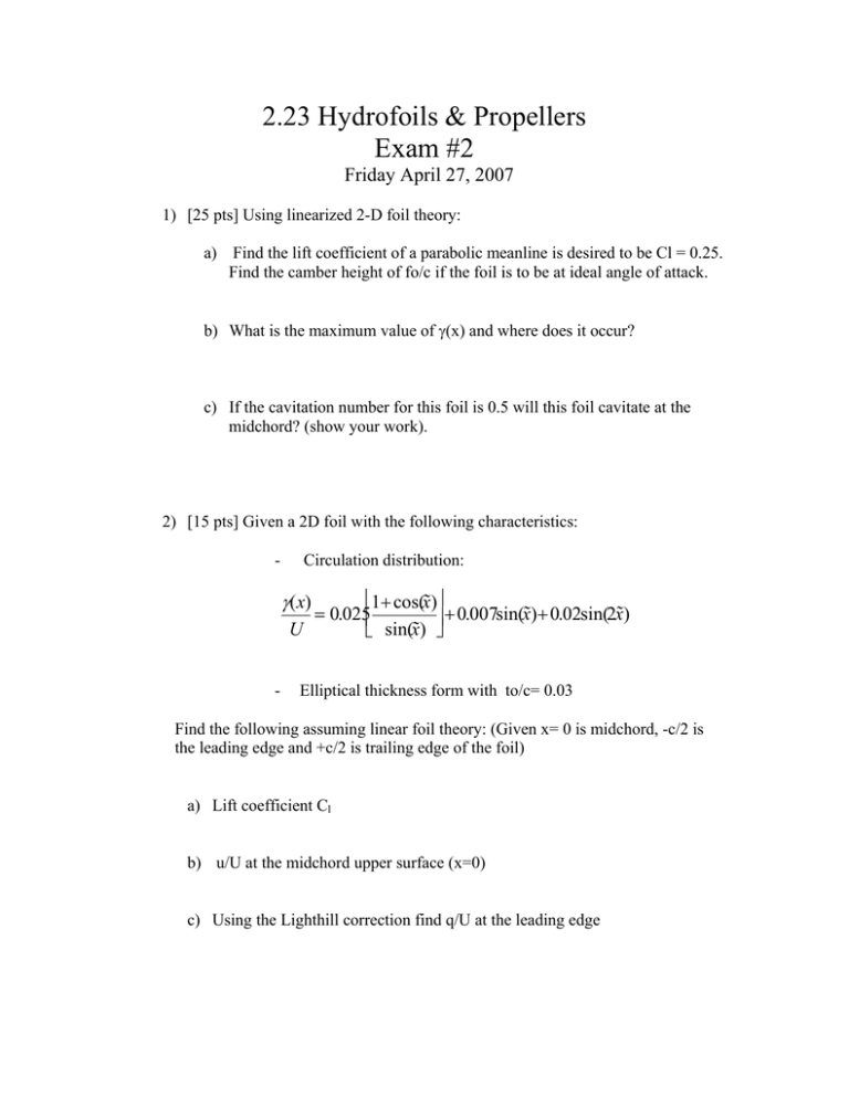
2.23 Hydrofoils & Propellers Exam #2 Friday April 27, 2007 1) [25 pts] Using linearized 2-D foil theory: a) Find the lift coefficient of a parabolic meanline is desired to be Cl = 0.25. Find the camber height of fo/c if the foil is to be at ideal angle of attack. b) What is the maximum value of γ(x) and where does it occur? c) If the cavitation number for this foil is 0.5 will this foil cavitate at the midchord? (show your work). 2) [15 pts] Given a 2D foil with the following characteristics: - Circulation distribution: ⎡1+ cos(x˜)⎤ = 0.025⎢ ⎥ + 0.007sin(x˜)+ 0.02sin(2x˜) U ⎣ sin(x˜) ⎦ γ(x) - Elliptical thickness form with to/c= 0.03 Find the following assuming linear foil theory: (Given x= 0 is midchord, -c/2 is the leading edge and +c/2 is trailing edge of the foil) a) Lift coefficient Cl b) u/U at the midchord upper surface (x=0) c) Using the Lighthill correction find q/U at the leading edge 3) [40 pts] A propeller blade section at r/R=0.7 is to be designed using the NACA data given in Figure 1 of the notes (copy provided for your convenience). A lifting line design of the propeller is performed and the results for the flow at this radius are: Radius = 0.7 m chord = 0.15 m Vin =8.0 m/s ωr = 25 m/s Ua*=0.8 m/s Ut*=- 2 m/s Circulation Γ = 0.8 m2/s Seawater density: 1000 kg/m3 Seawater vapor pressure: 2.34 kPa g = 9.81 m/s2 Atmospheric pressure: 101 kPa The foil is to operate at the ideal angle of attack and will experience changes of inflow of 3.5 degrees total (i.e variation in angle of attack). a) Find the Pitch angle and pitch for the section b) Find the required Lift Coefficient for the section c) Find the required Camber height fo/C to achieve the Lift Coefficient. d) Find the to/C for this foil to achieve the desired cavitation number using the Brockett Diagrams (show work on attached diagrams). e) Will this section cavitate in the varying inflow? Comment. 4) [20 pts] A system of two vortices and sources is used to represent a flat wing. The inflow comes in at an angle of attack of 5 degrees. The foil thickness at the first source is 0.3m and at the second source is 0.15m . of the “wing”. The inflow is 15 m/s and the geometry of the vortices and control point is shown below. Γ1 ,S1 Γ2 , S2 Control Point Uo=15m/s α =5 deg 1m 1m 1m a) Write the system of equations to solve for Γ1 and Γ2. b) Find Γ1 and Γ2 c) Find the total lift of the “wing” if in water (ρ=1000kg/m3).

