11. Fluid Jets 11.1
advertisement
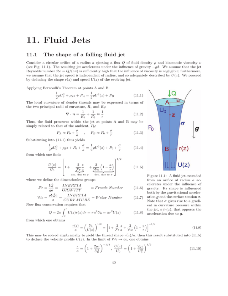
11. Fluid Jets 11.1 The shape of a falling fluid jet Consider a circular orifice of a radius a ejecting a flux Q of fluid density ρ and kinematic viscosity ν (see Fig. 11.1). The resulting jet accelerates under the influence of gravity −gẑ. We assume that the jet Reynolds number Re = Q/(aν) is sufficiently high that the influence of viscosity is negligible; furthermore, we assume that the jet speed is independent of radius, and so adequately described by U (z). We proceed by deducing the shape r(z) and speed U (z) of the evolving jet. Applying Bernoulli’s Theorem at points A and B: 1 2 1 (11.1) ρU + ρgz + PA = ρU 2 (z) + PB 2 2 0 The local curvature of slender threads may be expressed in terms of the two principal radii of curvature, R1 and R2 : 1 1 1 ∇·n= + ≈ (11.2) R2 r R1 Thus, the fluid pressures within the jet at points A and B may be simply related to that of the ambient, P0 : σ σ PA ≈ P0 + (11.3) , PB ≈ P0 + a r Substituting into (11.1) thus yields 1 2 σ 1 σ ρU + ρgz + P0 + = ρU 2 (z) + P0 + a 2 r 2 0 from which one finds 1/2 U (z) 1 + = U0 2 z Fr � a + acc. due to g 2 ( a ) 1− r �We (11.4) (11.5) dec. due to σ where we define the dimensionless groups IN ERT IA U02 = = F roude N umber ga GRAV IT Y IN ERT IA ρU02 a We = = = W eber N umber σ CU RV AT U RE Now flux conservation requires that Fr = (11.6) (11.7) r U (z)r(z)dr = πa2 U0 = πr2 U (z) Q = 2π 0 (11.8) Figure 11.1: A fluid jet extruded from an orifice of radius a ac­ celerates under the influence of gravity. Its shape is influenced both by the gravitational acceler­ ation g and the surface tension σ. Note that σ gives rise to a gradient in curvature pressure within the jet, σ/r(z), that opposes the acceleration due to g. from which one obtains r(z) = a ( U0 U (z) )1/2 [ ]−1/4 2 z 2 ( a) 1− = 1+ + Fr a We r (11.9) This may be solved algebraically to yield the thread shape r(z)/a, then this result substituted into (11.5) to deduce the velocity profile U (z). In the limit of We → ∞, one obtains ( )−1/4 ( )1/2 r 2gz U (z) 2gz = 1+ 2 , = 1+ 2 (11.10) U0 U0 a U0 40 11.2. The Plateau-Rayleigh Instability 11.2 Chapter 11. Fluid Jets The Plateau-Rayleigh Instability We here summarize the work of Plateau and Rayleigh on the instability of cylindrical fluid jets bound by surface tension. It is precisely this Rayleigh-Plateau instability that is responsible for the pinch-off of thin water jets emerging from kitchen taps (see Fig. 11.2). The equilibrium base state consists of an infinitely long quiescent cylindrical inviscid fluid column of radius R0 , density ρ and surface tension σ (see Fig. 11.3). The influence of gravity is neglected. The pressure p0 is constant inside the column and may be calculated by balancing the normal stresses with surface tension at the boundary. Assuming zero external pressure yields σ p0 = σ∇ · n ⇒ p0 = . (11.11) R0 We consider the evolution of infinitesimal varicose perturbations on the interface, which enables us to linearize the governing equations. The perturbed columnar surface takes the form: ˜ = R0 + ǫeωt+ikz , R (11.12) where the perturbation amplitude ǫ ≪ R0 , ω is the growth rate of the instability and k is the wave number of the disturbance in the zdirection. The corresponding wavelength of the varicose perturbations is necessarily 2π/k. We denote by ũr the radial component of the perturbation velocity, ũy the axial component, and p̃ the perturbation pressure. Substituing these perturbation fields into the N-S equations and retaining terms only to order ǫ yields: 1 ∂p̃ ∂ũr =− ∂t ρ ∂r ∂ũz 1 ∂p̃ =− ∂t ρ ∂z (11.13) (11.14) The linearized continuity equation becomes: Figure 11.2: The capillary-driven instability of a water thread falling under the influence of gravity. The initial jet diameter is approximately 3 mm. ∂ũr ũr ∂ũz + + =0 . (11.15) ∂r r ∂z We anticipate that the disturbances in velocity and pressure will have the same form as the surface dis­ turbance (11.12), and so write the perturbation ve­ locities and pressure as: ( ) (ũr , ũz , p̃) = R(r), Z(r), P (r) eωt+ikz . (11.16) Substituting (11.16) into equations (11.13-11.15) yields the linearized equations governing the per­ turbation fields: 1 dP ρ dr ik ωZ = − P ρ Momentum equations : ωR = − Continuity: dR R + + ikZ = 0 . dr r MIT OCW: 18.357 Interfacial Phenomena (11.17) (11.18) (11.19) Figure 11.3: A cylindrical column of initial radius R0 comprised of an inviscid fluid of density ρ, bound by surface tension σ. 41 Prof. John W. M. Bush 11.2. The Plateau-Rayleigh Instability Chapter 11. Fluid Jets Eliminating Z(r) and P (r) yields a differential equation for R(r): r2 ) d2 R dR ( +r − 1 + (kr)2 R = 0 . 2 dr dr (11.20) This corresponds to the modified Bessel Equation of order 1, whose solutions may be written in terms of the modified Bessel functions of the first and second kind, respectively, I1 (kr) and K1 (kr). We note that K1 (kr) → ∞ as r → 0; therefore, the well-behavedness of our solution requires that R(r) take the form R(r) = CI1 (kr) , (11.21) where C is an as yet unspecified constant to be determined later by application of appropriate boundary conditions. The pressure may be obtained from (11.21) and (11.17), and by using the Bessel function identity I ′ 0 (ξ) = I1 (ξ): ωρC ik (11.22) P (r) = − I0 (kr) and Z(r) = − P (r). k ωρ We proceed by applying appropriate boundary conditions. The first is the kinematic condition on the free surface: ∂R̃ = ũ · n ≈ ũr . (11.23) ∂t Substitution of (11.21) into this condition yields C= ǫω . I1 (kR0 ) (11.24) Second, we require a normal stress balance on the free surface: p0 + p̃ = σ∇ · n (11.25) ) + R12 , where R1 and R2 are the principal radii of curvature of ( We write the curvature as σ∇ · n = R11 the jet surface: 1 1 1 ǫ = ≈ − 2 eωt+ikz ωt+ikz R1 R0 R0 R0 + ǫe 1 = ǫk 2 eωt+ikz . R2 (11.26) (11.27) Substitution of (11.26) and (11.27) into equation (11.25) yields: p0 + p̃ = ) σ ǫσ ( − 2 1 − k 2 R02 eωt+ikz R0 R0 (11.28) Cancellation via (11.11) yields the equation for p̃ accurate to order ǫ: p̃ = − ) ǫσ ( 1 − k 2 R02 eωti kz . 2 R0 (11.29) Combining (11.22), (11.24) and (11.29) yields the dispersion relation, that indicates the dependence of the growth rate ω on the wavenumber k: ω2 = ) σ I1 (kR0 ) ( kR0 1 − k 2 R02 3 ρR0 I0 (kR0 ) (11.30) We first note that unstable modes are only possible when kR0 < 1 MIT OCW: 18.357 Interfacial Phenomena 42 (11.31) Prof. John W. M. Bush 11.3. Fluid Pipes Chapter 11. Fluid Jets The column is thus unstable to disturbances whose wavelengths exceed the circumference of the cylinder. A plot of the dependence of the growth rate ω on the wavenumber k for the Rayleigh-Plateau instability is shown in Fig. 11.4. The fastest growing mode occurs for kR0 = 0.697, i.e. when the wavelength of the disturbance is λmax ≈ 9.02R0 (11.32) By inverting the maximum growth rate ωmax one may estimate the characteristic break-up time: � ρR03 tbreakup ≈ 2.91 (11.33) σ Figure 11.4: The dependence of the growth rate ω on the wavenumber k for the Rayleigh­ Plateau instability. µν . Note: In general, pinch-off depends on Oh = σR ( 2 )1/2 ρR , λ = 9.02R. At low Oh, we have seen that τpinch ∼ σ At high Oh, when viscosity is important, τpinch ∼ µR σ , λ increases with µ. A water jet of diameter 1cm has a characteristic break-up time of about 1/8s, which is consistent with casual observation of jet break-up in a kitchen sink. Related Phenomena: Waves on jets When a vertical water jet impinges on a horizontal reservoir of water, a field of standing waves may be excited on the base of the jet (see Fig. 11.5). The wavelength is determined by the requirement that the wave speed correspond to the local jet speed: U = −ω/k. Using our dispersion relation (11.30) thus yields U2 = ) σ I1 (kR0 ) ( ω2 = 1 − k 2 R02 k2 ρkR02 I0 (kR0 ) (11.34) Provided the jet speed U is known, this equation may be solved in order to deduce the wavelength of the waves that will travel at U and so appear to be stationary in the lab frame. For jets falling from a nozzle, the result (11.5) may be used to deduce the local jet speed. 11.3 Fluid Pipes The following system may be readily observed in a kitchen sink. When the volume flux exiting the tap is such that the falling stream has a diameter of 2 − 3mm, obstructing the stream with a finger at a distance of several centimeters from the tap gives rise to a stationary field of varicose capillary waves upstream of the finger. If the finger is dipped in liquid detergent (soap) before insertion into the stream, the capillary waves begin at some critical distance above the finger, below which the stream is cylindrical. Closer inspection reveal that the surface of the jet’s cylindrical base is quiescent. An analogous phenomenon arises when a vertical fluid jet impinges on a deep water reservoir (see Fig. 11.5). When the reservoir is contaminated by surfactant, the surface tension of the reservoir is diminished relative to that of the jet. The associated surface tension gradient draws surfactant a finite distance up the jet, prompting two salient alterations in the jet surface. First, the surfactant suppresses surface waves, so that the base of the jet surface assumes a cylindrical form (Fig. 11.5b). Second, the jet surface at its base becomes stagnant: the Marangoni stresses associated with the surfactant gradient are balanced by the viscous stresses generated within the jet. The quiescence of the jet surface may be simply demonstrated by sprinkling a small amount of talc or lycopodium powder onto the jet. The fluid jet thus enters a contaminated reservoir as if through a rigid pipe. A detailed theoretical description of the fluid pipe is given in Hancock & Bush (JFM, 466, 285-304). We here present a simple scaling that yields the dependence of the vertical extent H of the fluid pipe on MIT OCW: 18.357 Interfacial Phenomena 43 Prof. John W. M. Bush 11.3. Fluid Pipes Chapter 11. Fluid Jets Figure 11.5: a) The field of stationary capillary waves excited on the base of a water jet impinging on a horizontal water reservoir. b) The fluid pipe generated by a falling water jet impinging on a contaminated water reservoir. The field of stationary capillary waves is excited above the fluid pipe. The grids at right are millimetric. the governing system parameters. We assume that, once the jet enters the fluid pipe, a boundary layer develops on its outer wall owing to the no-slip boundary condition appropriate there. Balancing viscous and Marangoni stresses on the fluid pipe surface yields ρν V Δσ ∼ , δH H (11.35) where Δσ is the surface tension differential between the jet and reservoir, V is the jet speed at the top of the fluid pipe, and δH is the boundary layer thickness at the base of the fluid pipe. We assume that the boundary layer thickness increases with distance z from the inlet according to classical boundary layer scaling: ( νz )1/2 δ ∼ . (11.36) a a2 V Thus, at the base of a pipe of height H δ(H) = ( νH a2 V )1/2 (11.37) Substituting for δ(H) from (11.36) into (11.35) yields H∼ (Δσ)2 ρµV 3 (11.38) The pipe height increases with the surface tension differential, and decreases with fluid viscosity and jet speed. MIT OCW: 18.357 Interfacial Phenomena 44 Prof. John W. M. Bush MIT OpenCourseWare http://ocw.mit.edu 357 Interfacial Phenomena Fall 2010 For information about citing these materials or our Terms of Use, visit: http://ocw.mit.edu/terms.
