Document 13516037
advertisement
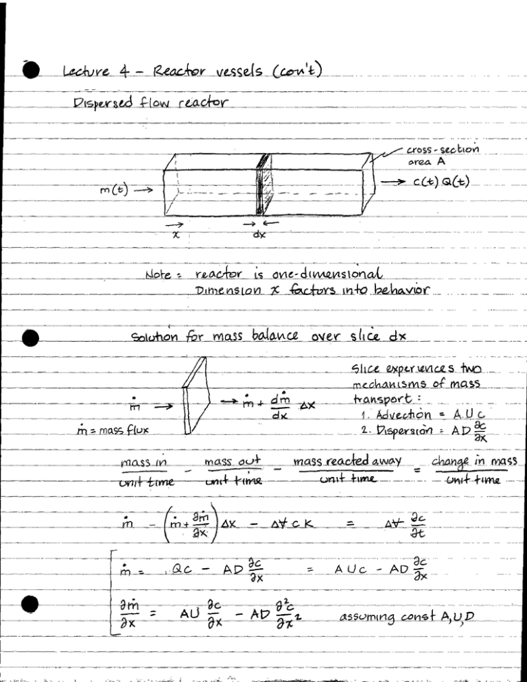
Dispersed flow reactor response to spike input Pe = ∞ c c0 t/tR Fraction remaining Dispersed-flow reactor performance for k = 0.5/day 1.0 0.9 0.8 0.7 0.6 0.5 0.4 0.3 0.2 0.1 0.0 Pe = 0 (FMT) Pe = 1 Pe = 2 Pe = 10 Pe = ∞ (PFR) 0 2 4 6 Residence time (days) 8 10 Dispersed-flow reactor performance for k = 0.5/day Fraction remaining 1.000 0.100 Pe = 0 (FMT) Pe = 1 Pe = 2 Pe = 10 Pe = ∞ (PFR) 0.010 0.001 0 2 4 6 Residence time (days) 8 10 Dimensionless concentration, c/c0 3 n=∞ 40 2.5 2 20 1.5 10 5 1 2 0.5 n=1 0 0 0.5 1 Dimensionless time, t/tR 1.5 2 Tanks-in-series compared to dispersed flow reactor Dispersed flow Tanks-in-series Tanks-in-series with exchange flow c c0 t/tR Residence Time Distributions We have seen two extreme ideals: Plug Flow – fluid particles pass through and leave reactor in same sequence in which they enter Stirred Tank Reactor – fluid particles that enter the reactor are instantaneously mixed throughout the reactor Residence time distribution - RTD(t) – represents the time different fractions of fluid actually spend in the reactor, i.e. the probability density function for residence time Q V Q Measure dye concentration at outlet Inject slug of dye at inlet at t=0 RTD( t) = C( t) (for steady flow) ∞ ∫ C(t)dt 0 Note units - RTD is in inverse time ∞ by definition: ∫ RTD(t)dt = 1 (i.e., total probability = 1) 0 ∞ tD = ∫ t RTD( t )dt = first moment of RTD = tracer detention time 0 Plug flow RTD = δ(t-tR) tR•RTD 1 CSTR RTD = 1/tR exp(-t/tR) 0.38 0.14 tR 2tR t RTD math: Dirac delta function (or unit impulse function) 15 Represents a unit mass concentrated into infinitely small space resulting in an infinitely large concentration δ(t) = ∞ at t = 0, 0 at t ≠ 0 ∞ ∫ δ( t )dt = 1 −∞ Can think of Dirac delta function as extreme form of Gaussian M0δ(t-τ) is spike of mass M0 at time τ Plug Flow RTD(t) = δ(t-tR) with implied units of t-1 ∞ ∞ 0 0 ∫ RTD(t )dt = ∫ δ(t − t R )dt = 1 zeroth moment Note lower limit is 0 and not -∞ since you can’t have negative residence time (i.e., fluid leaving before it entered) ∞ ∞ 0 0 tD = ∫ t RTD( t )dt = ∫ t δ( t − tR )dt = tR first moment (mean) = tracer detention time CFSTR RTD(t) = exp(-t/tR) / tR units of t-1 ∞ ∞ ∞ ⎡ exp( − t / t R ) ⎤ ⎡ exp( − t / t R ) exp(0) ⎤ RTD ( t ) dt dt t t 0 = = − = − − R R ⎢ ⎥ ⎢ ⎥ =1 ∫0 ∫0 t R t t R R ⎣ ⎦0 ⎣ ⎦ ∞ ⎤ exp( −t / tR ) 1 ⎡ exp( − t / tR ) (− t / tR − 1)⎥ tD = ∫ t RTD( t )dt = ∫ t dt = ⎢ 2 tR tR ⎣ 1 tR 0 0 ⎦0 = tR [0 − exp(0)(− 0 − 1)] = tR ∞ ∞ Note: from CRC Tables: ∫ xe ax dx = e ax ( ax − 1 ) a2 Control Volume Models and Time Scales for Natural Systems What are actual systems like? Plug flow or Stirred reactor It depends upon the time scales: Mixing time for plug flow reactor is infinite: it never mixes Mixing time for stirred reactor is zero: it mixes instantaneously When are these assumptions realistic? We need to estimate the time of the real system to mix - tMIX compared to time to react If tMIX << tR → stirred reactor If tMIX >> tR → plug flow reactor 16 Residence Time and Reactions RTD provides a means to estimate pollutant removal Consider a 1st-order reaction: C(t) = C0 exp(-kt) This reaction applies to any water mass entering and exiting the system – view from Lagrangian perspective (i.e., following the parcel of water) t2 t1 t3 t4 Exit concentration: Ce = C0 exp(-kt4) Consider a different parcel, taking a longer route: Exit concentration Ce=C0 exp(-kt6) where t6 > t4 t2 t1 t3 t4 t2 t3 t4 t5 t6 If a plug flow model applies, the exit concentration is simple: all parcels exit at exactly TR In a natural system, it is not perfect plug flow, therefore look at RTD RTD gives the probability that the fluid parcel requires a given amount of time to pass system On average: ∞ ∫ C e = RTD( t ) C 0 exp( −kt )dt 0 At t1 Ce = C0 exp(-kt1) RTD At t2 Ce = C0 exp(-kt2) t1 t t2 17 Residence Time Distribution for Real Systems QR CI At inlet Recirculation QR Ce At outlet Real circulation has: Short circuiting Dead zones (exclusion zones) RTD from tracer study ≠ plug flow or stirred tank reactor RTD tD t tR Detention time, TD ∞ tD = ∫ tRTD(t )dt 0 Note distinction with hydraulic residence time, tR = V/Q tD = tR if and only if there are no exclusion zones Variance of RTD is a measure of mixing ∞ σ = ∫ ( t − t D ) 2 RTD( t ) dt 2 0 ⎛σ As a dimensionless number, d = ⎜⎜ ⎝ tD ⎞ ⎟⎟ ⎠ 2 RTD σ t As σ → 0, no mixing, plug flow As σ → ∞, complete mixing, CFSTR 18 Residence Time Distribution for Real Systems Review some concepts: Two models for mixing Plug flow Stirred reactor Time scales: tR = V/Q mean hydraulic residence time (nominal residence time) tREACTION =1/k (or for 95% complete reaction or removal 3/k) tADV = L/u Limitations of tR in describing residence times of true systems because of dead zones, recirculation, short circuiting Consider alteration of the real system: Add berms to control circulation! 19 Lecture 4.doc Figure by MIT OCW. Adapted from: Camp, T. R. "Sedimentation and the design of settling tanks." Transactions ASCE 111 (1946): 895-936.
