- + A v
advertisement

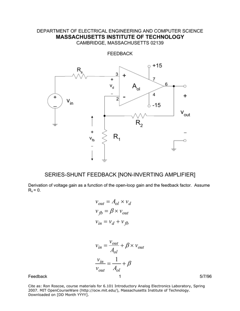
DEPARTMENT OF ELECTRICAL ENGINEERING AND COMPUTER SCIENCE MASSACHUSETTS INSTITUTE OF TECHNOLOGY CAMBRIDGE, MASSACHUSETTS 02139 FEEDBACK +15 Rs 3 + + vd + _ 6 Aol – 2 vin 7 4 - + -15 vout R2 _ + vfb R1 – SERIES-SHUNT FEEDBACK [NON-INVERTING AMPLIFIER] Derivation of voltage gain as a function of the open-loop gain and the feedback factor. Assume Rs = 0. vout = Aol × vd v fb = β × vout vin = vd + v fb vout + β × vout Aol 1 = +β Aol vin = vin vout Feedback 1 5/7/96 Cite as: Ron Roscoe, course materials for 6.101 Introductory Analog Electronics Laboratory, Spring 2007. MIT OpenCourseWare (http://ocw.mit.edu/), Massachusetts Institute of Technology. Downloaded on [DD Month YYYY]. vin = 1 + βAol vout 1 + βAol = Aol Aol × vin vout vout Aol = ; vin 1 + βAol if βAol >> 1, vout 1 = vin β then: (1 + βAol ) is known as the β= R1 ; R1 + R2 1 β = feedback factor R1 + R2 R = 1+ 2 R1 R1 If, at some frequency, the magnitude of Aol falls to 10,000, and you expect a closed loop gain of 1000 from the amplifier (β=.001, 1/β=1000=103=60dB), the actual closed loop gain will be: vout Aol 104 104 = = = = 909 = 59.2dB vin 1 + βAol 1 + 10−3 × 10⁴ 11 In general, the series connection raises amplifier characteristics by the amount of the feedback factor; the shunt connection reduces amplifier characteristics by the amount of the feedback factor. Therefore, at this certain frequency where (1+βAol)=11, for this amplifier configuration, the input impedance will be 11 times higher than the input impedance of the opamp without feedback, and the output impedance will be 11 times lower than the output impedance of the opamp without feedback. The bandwidth of the amplifier is increased by a factor of 11, and of course, the open loop gain is decreased by a factor of 11. Considering the open-loop gain bandwidth plot of a 741, it is easy to see that building an amplifier with a gain of 1000 at low frequencies using a 741 is a foolish endeavor, since increasing the bandwidth 11 times only moves the upper 3dB point from 10 Hz to about 110 Hz.!!! Using the normal, typical low frequency Aol for the 741 = 100,000, the feedback factor would become 101 for this 60 dB amplifier, so now we would be able to increase our high frequency rolloff point out to about 1000 Hz!!! Feedback 2 5/7/96 Cite as: Ron Roscoe, course materials for 6.101 Introductory Analog Electronics Laboratory, Spring 2007. MIT OpenCourseWare (http://ocw.mit.edu/), Massachusetts Institute of Technology. Downloaded on [DD Month YYYY]. For this shunt-series connection, feedback always stabilizes voltage gain, raises input impedance and lowers output impedance, all by [1+βAol]. Thus, this configuration is an ideal voltage amplifier or voltage source. THE GOLDEN RULES OF OP-AMPS (From Horowitz & Hill, page 177) 1. Assuming the op-amp voltage is so high that a fraction of a millivolt between the input terminals will swing the output over its full range, we can ignore that small voltage and state golden rule one: The output attempts to do whatever is necessary to make the voltage difference between the inputs zero. Note: This does not mean that the op-amp actually changes the voltage at its input. What it does is “look” at its input terminals and swing its output terminal around so that the external feedback network brings the input differential to zero whenever possible. 2. Assuming that op-amps draw very little input current (nanoamps to picoamps), we round this down and state: The inputs draw no current. Note: They must have some DC current or the op-amp won’t work, so a corollary to this rule is that you must ALWAYS provide a DC current path to both inputs. BENEFITS OF FEEDBACK STABILIZE GAIN AGAINST DEVICE VARIATIONS, TEMPERATURE, AGING MANIPULATE INPUT AND OUTPUT IMPEDANCES BY FEEDBACK FACTOR [1+βAol] REDUCE DISTORTION BY THE FEEDBACK FACTOR [1+βAol] INCREASE BANDWIDTH BY THE FEEDBACK FACTOR [1+βAol] TYPICAL FEEDBACK FACTOR FOR 741 [Aol = 100,000] A=60 dB =1000; β=0.001; [1+βAol] = 101 A=20 dB = 10; β=0.1; [1+βAol] = 10,001 A=0 dB = 1; β=1; [1+βAol] = 100,001 A=40 dB =100; β=0.01; [1+βAol] = 1001 A=10 dB = 3.16; β=0.32; [1+βAol] = 31,622 DISADVANTAGES OF FEEDBACK LOSS OF GAIN; NEED MORE STAGES GREATER TENDENCY TO OSCILLATE Feedback 3 5/7/96 Cite as: Ron Roscoe, course materials for 6.101 Introductory Analog Electronics Laboratory, Spring 2007. MIT OpenCourseWare (http://ocw.mit.edu/), Massachusetts Institute of Technology. Downloaded on [DD Month YYYY]. +15 Rs 3 + vd + _ 7 6 Ay – vin + 2 4 -15 Io RL + vout _ + vfb RF – SERIES-SERIES FEEDBACK [NON-INVERTING AMPLIFIER, FLOATING LOAD, HIGH OUTPUT IMPEDANCE] Feedback 4 5/7/96 Cite as: Ron Roscoe, course materials for 6.101 Introductory Analog Electronics Laboratory, Spring 2007. MIT OpenCourseWare (http://ocw.mit.edu/), Massachusetts Institute of Technology. Downloaded on [DD Month YYYY]. vin = vd + v fb vd = io Ay v fb = io RF ; ⎛ 1 ⎞ io ∴ vin = + io RF = io ⎜⎜ + RF ⎟⎟ Ay A ⎝ y ⎠ ⎞ vin ⎛ 1 =⎜ + RF ⎟⎟ io ⎜⎝ Ay ⎠ Ay vin io = 1 + Ay RF ; inverting: Ay io 1 = ≈ vin 1 + Ay RF RF Feedback 5 5/7/96 Cite as: Ron Roscoe, course materials for 6.101 Introductory Analog Electronics Laboratory, Spring 2007. MIT OpenCourseWare (http://ocw.mit.edu/), Massachusetts Institute of Technology. Downloaded on [DD Month YYYY].


