L · /,.: Al A
advertisement
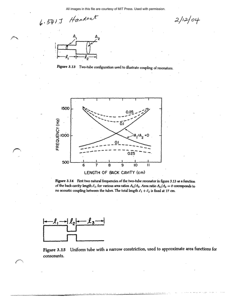
All images in this file are courtesy of MIT Press. Used with permission. ,1~nCo~ L·- /,.: gl'a10Lr Al 3.3 Figure 3.I3 A2 wo-tbe guraton used to llustrate couplng of resonators. Two-tube configuration used to illustrate coupling of resonators. I I I I I 1500 N >- z w oo000 w It .LL 0.25 =JV) ,, I I I I I I 6 7 -8 9 10 II LENGTH OF BACK CAVITY (cm) Figure 3.14 First two natural frequencies.of the two-tube resonator in figure 3.13 as a function of the back-cavity length , for various area ratios A/A 2 . Area ratio A/A 2 = corresponds to no acoustic coupling between the tubes. The total length t + 2 is fixed at 17 cn. Figure 3.15 consonants. -· -·- · Uniform tube with a narrow constriction, used to approximate area functions for A F40 N I F30 Z21 0 w F20 W Cr U­ FIO 8 10 2 4 6 LENGTH OF BACK CAVITY,, 0 14 12 (cm) Figure 3.16 Relations between natural frequencies and the position of the constriction for the configuration shown in figure 3.15. The overall length of the tube is 16 cm and the length of the constriction is 2 cm. The lines sloping up to the right represent the resonances of the front cav­ ity (anterior to the constriction); the lines sloping down to the right represent the resonances of the back cavity. The solid lines are the resonances if there is no coupling between front and back cavities. The dashed lines near the point of coincidence of two resonances at el = 9.3 cm illus­ trate the shift in the resonant frequencies for the case where there is a small amount of coupling between front and back cavities. When the area of the constriction is very small, Fl = 0 as shown. When the constriction is larger, F1 increases as shown by the dashed line. The reso­ nances of a 16-cman tube with no constriction are shown by the labeled marks at the right. The curves are labeled with the appropriate formant numbers. 20 - to o (aj 0 7r 27' 37r 47r 27T f C I I I I 20 -- (b) o - o o0 0 0 I I I I I 2 3 4 FREQUENCY (kHz) Figure 3.31 (a) Plot of magnitude of transfer function T(f) = Uo/U, expressed in decibels for an ideal uniform, lossless acoustic tube, shown in figure 3.8. (b) Magnitude of transfer function T(f) for an ideal uniform tube of length 15 cm with losses similar to those occurring in the vocal tract. .--L1,·--rn-·-·---- .�___--D-·�i�_*-.iZ·Pli�t�a
