Massachusetts Institute of Technology
advertisement

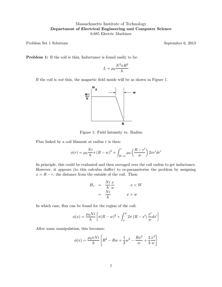
Massachusetts Institute of Technology Department of Electrical Engineering and Computer Science 6.685 Electric Machines Problem Set 1 Solutions September 6, 2013 Problem 1: If the coil is thin, Inductance is found easily to be: L = µ0 N 2 πR2 h If the coil is not thin, the magnetic field inside will be as shown in Figure 1. H z w Ni h R Figure 1: Field Intensity vs. Radius Flux linked by a coil filament at radius r is then: Ni π (R − w)2 + φ(r) = µ0 h l r µ0 R−w � R − r′ 2πr ′ dr ′ w � In principle, this could be evaluated and then averaged over the coil radius to get inductance. However, it appears (to this calculus duffer) to re-parameterize the problem by assigning x = R − r, the distance from the outside of the coil. Then: Hz = = Ni x h w Ni h x<W x>w In which case, flux can be found for the region of the coil: µ0 N i φ(x) = π(R − w)2 + h [ l w x x′ ′ 2π R − x dx w ( ′) After some manipulation, this becomes: φ(x) = µ0 πN i 1 Rx2 2 x3 + R2 − Rw + w2 − h 3 w 3w 1 ] then inductance is found by averaging φ over the extent of the coil, and with a few steps of grunge left out: L = = = 1 wN φ(x)dx i 0 w " # l µ0 πN 2 W 1 2 Rx2 2 x3 2 R − Rw + w − + dx 3 w 3w hw 0 l " 4w 1 µ0 πN 2 R2 1− + h 3R 2 � w R � 2 # Problem 2: With a steady DC current, field along the centerline is simply: H0 = Ni h In the event of a transient, Faraday’s Law can be used: - · d-ℓ = − d E dt ll - · -nda B Taking this integral within the conductive cylinder at radius Rc , this is: 2πRc d (Hi − H0 ) + πRc2 µ0 Hi = 0 σ dt where Hi is the field inside and H0 = Ni h is the field outside the shell. The shell time constant is identified: Ts = µ0 σts Rc 2 and the differential equation for field is: Ts Driven by a step of Ho = d Hi + Hi = Ho dt Ni h u(t), Hi = t � Ni � 1 − e− Ts h This is shown in Figure 2 To find the response of the field inside the shell, see that the symmetrical triangle wave can be expressed as the sum of two waveforms, each consisting of a ramp and a constant value, as shown in Figure 3. This observation allows us to calculate the magnetic field once and then add the same solution, inverted in sign and delayed. First, we solve the field problem for the first excitation, consisting of a ramp of length T and NI I a slopt of N hT , followed by a constant value of h . During the ramp, since the ramp is the integral of the step, the response is the integral of the step response, and for the period after the end of the ramp, the solution follows a simple first-order response to the steady state field: 2 4 10 Problem 1.2, part 2a x 10 9 8 7 A/m 6 5 4 3 2 1 0 0 0.005 0.01 0.015 0.02 0.025 0.03 time, sec 0.035 0.04 0.045 0.05 Figure 2: Step Response Figure 3: Addition of two waves to form the triangle H(t) = H0 [ [ t τ � t − Tτ 1 − e − τ � � T �] H(t) = H0 1 − Tτ 1 − e − τ e− 0 < t < T ] t−T t > T τ It is straightforward to combine this solution with its inverted and shifted version, and now there are three time regions: H(t) = H0 [ � � T [ t τ H(t) = H0 1 − Tτ 1 − e − τ e − H(t) = � � t − Tτ 1 − e− τ ] t−T τ − H0 � T 2 H0 Tτ 1 − e− τ [ �] t−T T e− 0 < t < T � − Tτ 1 − e − t−2T τ � ] t−T τ T < t < 2T 2T < t This is shown in Figure 4, along with the triangle wave that would be the field were the shell not there. Finally (for this problem), we must find coil voltage. Since the coil has resistance and links time varying flux, we have: v(t) = Rw I(t) + 3 dλ dt 4 10 6.685 Problem 1, Axial Field x 10 Outer Inner 9 8 7 A/m 6 5 4 3 2 1 0 0 0.005 0.01 0.015 0.02 0.025 Time, Seconds 0.03 0.035 0.04 Figure 4: addition of two waves to form the triangle Coil resistance is found by Rw = ℓw /σAw . ℓw is total wire length, and it is found my multiplying average wire length by the number of turns: w N ℓw = 2π R − 2 � � Wire area Aw is found by multiplying the coil cross section by space factor and dividing by the number of turns: Aw = hwλa N So coil resistance is 2π R − w2 N 2 Rw = hwλa ( ) To find flux, we can observe that total flux linkage can be expressed as the sum of flux inside of the shell, which we have just calculated, plus flux that would be linked by the inductance that would exist were the region of the shell to be perfectly diamagnetic. That inductance is found by a minor modification of the calculation of inductance above: µ0 πN 2 L0 = h 2 R − Rc2 4w 1 − + 3R 2 � w R 2 � To find the rate of change of flux within the shell, we could either differentiate the field we found above or take advantage of the fact that the response to the derivative of a function is the derivative of the response to that function, and note that the derivative of the exciting current is two steps. In either case, we get the derivative of the magnetic field inside the shell: 4 ˙ H(t) � − Tτ Ḣ(t) = Hd 1 − e Ḣ(t) � t = Hd 1 − e− τ � − t−T τ e 0<t<T � − t−T τ − Hd 1 − e � T 2 � � = −Hd 1 − e− τ e− t−2T τ � T < t < 2T 2T < t where Hd is the slope of the magnetic field that would exist in the absence of the shell (the driving field): Hd = NI hT With these fragments, we can calculate voltage: v(t) = Rw i(t) + L0 di + λ˙s dt where the derivative of shell linked flux is: λ˙s (t) = πRc2 N µ0 Ḣ(t) The grungy calculations are carried out by a Matlab script that is appended. The three components of voltage are shown in Figure 5 and the final terminal voltage is shown in Figure 6. For the dimensions given in the problem set, parameters turn out to be: Resistance Inductance L0 (excluding the shell region Inductance L (without the shell) Approximate Inductance (ignoring coil thickness) 40.8 1.08 1.47 1.58 Ω H H H Problem 3 (Note this problem is mis-labeled in the original problem set as Problem 4) Rotational speed is: Ω = 2π × 10, 000 ≈ 1047Radians/sec 60 and then torque is: T = Rotor volume is VR = 10, 000 ≈ 9.55N-m 1047 T 9.55 = = 4.77 × 10⁻⁴ m3 2τ 10, 000 If rotor speed RΩ = 230 m/s, R = .22 m. and then rotor length is: ℓ= 4.77 × 10⁻⁴ ≈ .0031m π × .222 This is a kind of strange machine! We would probably seek some other morphology... 5 6.685 Problem 1 Resitive 600 400 200 0 0 0.005 0.01 0.015 0.02 0.025 0.03 0.035 0.04 0 0.005 0.01 0.015 0.02 0.025 0.03 0.035 0.04 0 0.005 0.01 0.015 0.02 0.025 Time, Seconds 0.03 0.035 0.04 Inductive 2000 1000 0 −1000 −2000 Inside Shell 400 200 0 −200 −400 Figure 5: Components of Voltage 6.685 Problem 1 2000 1500 1000 Volts 500 0 −500 −1000 −1500 0 0.005 0.01 0.015 0.02 0.025 Time, Seconds 0.03 Figure 6: Coil Terminal Voltage 6 0.035 0.04 % 6.685, Fall 2013 Problem Set 1, Problem 2 h = .1; % height R = .2; % coil outer radius w = .01; % coil thickness R_c = .1; % shell radius sig = 6e7; % shell conductivity ts = .001; % shell thickness muzero = 4e-7*pi; % permeability of free space N = 1000; % turns in the coil lama = 0.5; % winding factor for the coil tt = .01; % transient time tau = R_c*sig*ts*muzero/2; % shell time constant I_0 = 10; fprintf(’Problem 1, part 3 tau = %g\n’, tau) H_0 =N*I_0/h; Hdot_0 = H_0/tt; t = 0:.0001:.04; % this is the steady state field % this is magnitude of outer field derivative % going to plot over this range of time I = zeros(size(t)); Idot = zeros(size(t)); Ha = zeros(size(t)); H = zeros(size(t)); Hdot = zeros(size(t)); for k = 1:length(t); if t(k)<tt, Ha(k) = H_0 * t(k)/tt; H(k) = H_0 * (t(k)/tt - (tau/tt)*(1 - exp(-t(k)/tau))); Hdot(k) = Hdot_0 * (1 - exp(-t(k)/tau)); I(k) = I_0 * t(k)/tt; Idot(k) = I_0/tt; elseif t(k)<2*tt Ha(k) = H_0*(1-(t(k)-tt)/tt); H(k) = H_0 * (1 - exp(-(t(k)-tt)/tau)*(tau/tt)*(1-exp(-tt/tau))... -((t(k)-tt)/tt - (tau/tt)*(1-exp(-(t(k)-tt)/tau)))); Hdot(k) = Hdot_0 * ((1 - exp(-tt/tau)) * exp((-t(k)-tt)/tau)... -(1 - exp(-(t(k)-tt)/tau))); I(k) = I_0 * (1 - (t(k)-tt)/tt); Idot(k) = - I_0/tt; else Ha(k) = 0; H(k) = H_0*(tau/tt)*exp(-(t(k)-2*tt)/tau)*(1-exp(-tt/tau))^2; Hdot(k) = -Hdot_0 * (1 - exp(-tt/tau))^2 * exp(-(t(k)-2*tt)/tau); 7 I(k) = 0; Idot(k) = 0; end end % so now plot magnetic field through the shield figure(1) plot(t, Ha, t, H) title(’6.685 Problem 1, Axial Field’) ylabel(’A/m’) xlabel(’Time, Seconds’) legend(’Outer’, ’Inner’) % Now get the parameters of the system % winding resistance Rw = 2*pi*(R-w/2)*N^2/(h*w*lama*sig); % Inductance of outer part L_0 = (muzero*pi*N^2/h) * (R^2 - R_c^2 - (4/3)*R*w + .5 * w^2); fprintf(’Winding Resistance = %g Ohms\n’, Rw); fprintf(’Inductance (excluding inside shell = %g H\n’, L_0) L_t = (muzero*pi*N^2/h) * (R^2 - (4/3)*R*w + .5 * w^2); L_a = (muzero*pi*N^2/h) * R^2; fprintf(’Inductance, total = %g\n’, L_t); fprintf(’Inductance, Approximate = %g\n’, L_a); % voltage from flux linkage from inside the shell Vr = Rw .* I; Vl = L_0 .* Idot; Vi = pi*R_c^2 * N * muzero .* Hdot; V = Vr + Vl + Vi; figure(2) plot(t, Vr, t, Vl, t, Vi, t, V); title(’6.685 Problem 1, Voltages’) ylabel(’Volts’) xlabel(’Time, Seconds’) legend(’Resistance’, ’Inductance’, ’Inside Shell’, ’Total’) figure(3) subplot 311 plot(t, Vr); 8 title(’6.685 Problem 1’) ylabel(’Resitive’) subplot 312 plot(t, Vl); ylabel(’Inductive’) subplot(313) plot(t, Vi) ylabel(’Inside Shell’) xlabel(’Time, Seconds’) figure(4) clf plot(t, V); title(’6.685 Problem 1’) ylabel(’Volts’) xlabel(’Time, Seconds’) 9 MIT OpenCourseWare http://ocw.mit.edu 6.685 Electric Machines Fall 2013 For information about citing these materials or our Terms of Use, visit: http://ocw.mit.edu/terms.


