Document 13491555
advertisement
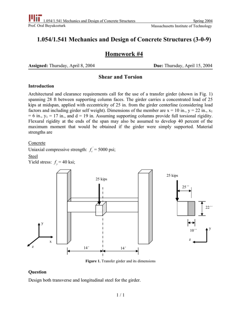
1.054/1.541 Mechanics and Design of Concrete Structures Prof. Oral Buyukozturk Spring 2004 Massachusetts Institute of Technology 1.054/1.541 Mechanics and Design of Concrete Structures (3-0-9) Homework #4 Assigned: Thursday, April 8, 2004 Due: Thursday, April 15, 2004 Shear and Torsion Introduction Architectural and clearance requirements call for the use of a transfer girder (shown in Fig. 1) spanning 28 ft between supporting column faces. The girder carries a concentrated load of 25 kips at midspan, applied with eccentricity of 25 in. from the girder centerline (considering load factors and including girder self weight). Dimensions of the member are x = 10 in., y = 22 in., x1 = 6 in., y1 = 17 in., and d = 19 in. Assuming supporting columns provide full torsional rigidity. Flexural rigidity at the ends of the span may also be assumed to develop 40 percent of the maximum moment that would be obtained if the girder were simply supported. Material strengths are Concrete ' Uniaxial compressive strength: f c = 5000 psi; Steel Yield stress: f y = 40 ksi; 25 kips 25 kips 25’’ 22’’ y 10’’ z x z 14’ 14’ Figure 1. Transfer girder and its dimensions Question Design both transverse and longitudinal steel for the girder. 1/1 y

![R09 Milford_Haven_Bridge_collapse[1].doc](http://s2.studylib.net/store/data/015465362_1-bb07aa6fdf59abd6cc2325f232e56032-300x300.png)
