Assignment 4 – Simulation Studies

MIT 4.430 Daylighting
Assignment 4 – Simulation Studies
The goal of this assignment is for you to learn more the simulation parameters and material modifiers in Radiance.
Task 4.1: Simulation Parameter Study (Individual Assignment)
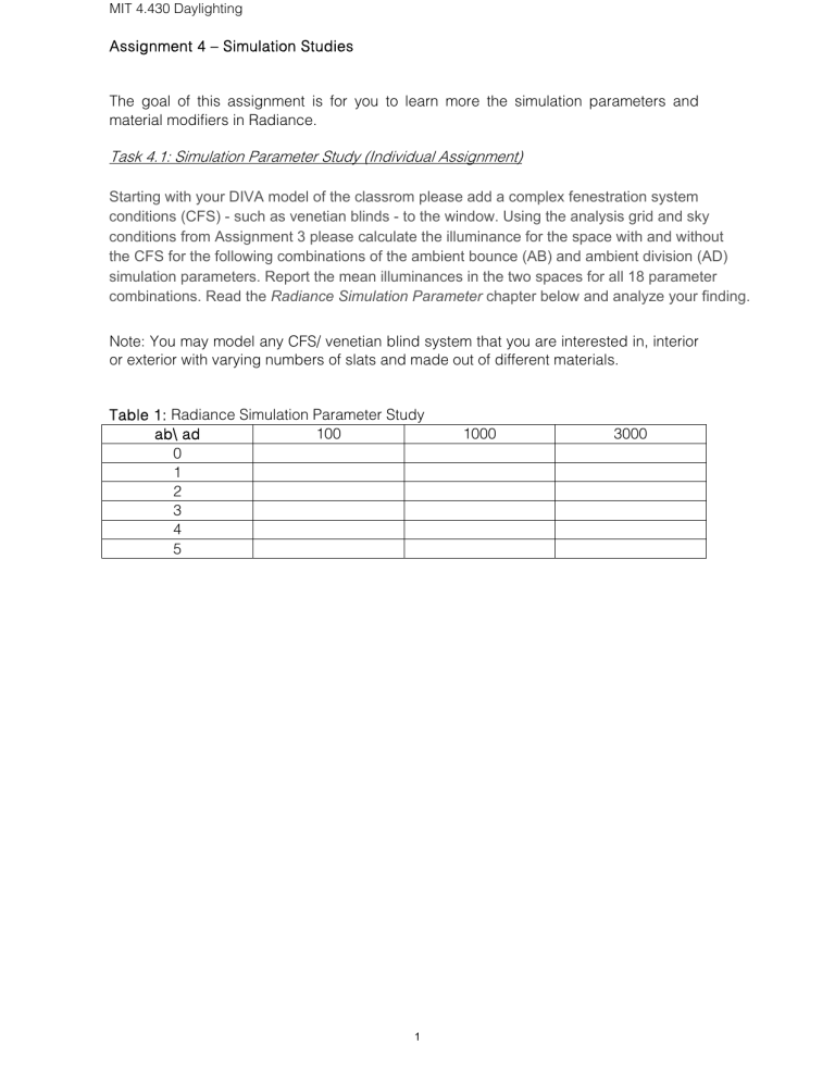
Starting with your DIVA model of the classrom please add a complex fenestration system conditions (CFS) - such as venetian blinds - to the window. Using the analysis grid and sky conditions from Assignment 3 please calculate the illuminance for the space with and without the CFS for the following combinations of the ambient bounce (AB) and ambient division (AD) simulation parameters. Report the mean illuminances in the two spaces for all 18 parameter combinations. Read the Radiance Simulation Parameter chapter below and analyze your finding.
Note: You may model any CFS/ venetian blind system that you are interested in, interior or exterior with varying numbers of slats and made out of different materials.
Table 1: Radiance Simulation Parameter Study ab\ ad 100 1000 3000
0
1
2
3
4
5
1
MIT 4.430 Daylighting
Appendix: Radiance Simulation Parameters
Extract from the Daysim Manual
A major hurdle for all Radiance novices is that the program requires the setting of a large number of simulation parameters which have few readily apparent real world correlates. Unfortunately, a wrong setting of some simulation parameters can completely compromise the accuracy of a simulation. To make matters worse,
Radiance does neither generate any warnings if an inadequate set of parameters has been chosen nor does it estimate the calculation errors. This can turn out to be a real problem as simulation results can lie above
or
below the true illuminance levels.
Simulation results are too low if Radiance misses a small window or skylight in a room and therefore grossly underestimates the real illuminance. Results are too high if
Radiance interpolates between two bright luminances directions, e.g. from two neighboring windows, and ignores that a wall lies in the interpolated region.
What is a simulation parameter?
RADIANCE is a backward raytracer , i.e. light paths are traced backward from the spectator’s eye to the light s principle, forward raytracing could be employed just the same, but for a great number of scenes the former ap more economical considering the required calculation times. The Radiance simulation parameters are a set of that can be individually set for each simulation. The parameters guide Radiance how to carry out a simulation. intuitive parameter is the number of “ambient bounce” (ab). The parameter instructs Radiance how many surfa bounce of or transmit through before it is discarded by Radiance. A detailed description of all simulation para
Radiance program “rtrace” can be found under http://radsite.lbl.gov/radiance/man_html/rtrace.1.html
.
In the following, three typical scenes of varying complexity are described and a set of simulation parameters is suggested for each scene. As stated in the beginning, the purpose of these scenes is to get you started. You are urged to further consult the excellent discussion on daylight simulations using Radiance in chapter 6 of the
Radiance book written by John Mardaljevic.
Remember...
While you can always choose a higher set of simulation parameters in Radiance, e.g. increase the number of ambient bounces, the “art” of using Radiance effectively is to you an adequate set of parameters that yields reliable results in a “justifiable” time frame. What would be a justifiable time frame for an annual daylight simulation using Daysim? The following table provides some ballpark numbers for the different scenes described below. The numbers assume that you run your simulations under
Windows on a 1GHz processor. Of course, these simulation times highly depend on the complexity of your building model. scene complexity scene 1: a room bordering the building envelop. The envelop consists of basic translucent, transparent and opaque elements without any complicated daylighting systems such as blinds or laser cut panels. scene 2: a space featuring complex daylighting systems with diffuse surfaces which require higher Radiance simulation parameters scene 3: a space featuring complex daylighting systems with highly specular surfaces simulation time
~ 15 minutes
~1-2 hours
12 hours or more
2
MIT 4.430 Daylighting scene 1
Assume that your goal is to calculate the annual illuminance profile due to daylight at a reference point behind a window in a particular office in a large building (see below).
Using forward raytracing the majority of traced rays would not even enter the room of interest (marked with a red ‘x’), i.e. the rays would be worthless for the calculation as they cannot contribute to the illuminance at the reference point. In this situation, starting from the reference point – using a standard Radiance simulation – is more economical. forward raytracing backward raytracing
For such a scene, the following simulation parameters should yield reliable results. The individual parameters are further described below. ambient bounces ambient division ambient sampling ambient accuracy ambient resolution direct threshold direct sampling
Further justifications for the choice of parameters... ambient bounces (ab=5): This parameter describes the number of diffuse inter-reflections which will be calculated before a ray path is discarded. An ab-value of 5 is already sufficient for a standard room without any complicated facade elements. This parameter significantly increases the required calculation time and should be set with care. It has to be even higher if interior rooms of facades including venetian blinds are considered, as rays may be reflected several times they find their way out of the building. ambient division (ad=1000) and ambient sampling (as=20): The ad-parameter determines the number of sample rays that are sent out from a surface point during an ambient calculation. This parameter needs to be high if the luminance distribution in a scene with a high brightness variation. An ambient sampling parameter greater than zero determines the number of extra rays that are sent in sample areas with a high brightness gradient. ambient accuracy (aa=0.1) and ambient resolution (ar=300): The combination of these two parameters with the maximum scene dimension provides a measure of how fine the luminance distribution in a scene is calculated. According to page 385 in Rendering with Radiance , the combination of aa=0.1, ar=300 and a maximum scene dimension of 100m yields a minimum spatial resolution for cached irradiances of: max
imum scene
dim
ension ambient x ambient resolution accuracy
The simulation resolution will be (100m
0.1)/300~3cm. This is sufficient if the facade/roof openings through which the daylight enters the building feature no details below 3 cm. The formula reveals that it is advantageous to keep your scene dimensions as small as possible. direct threshold (dt=0): This option switches off the selective source testing, i.e. each light source is equally considered during each shadow testing. This option is automatically set to zero when direct
3
MIT 4.430 Daylighting daylight coefficients are calculated using DAYSIM. direct sub sampling (ds=0): This option switches off the direct sub sampling threshold, i.e. only one ray is always send into the center of each light source. As during the calculation of the direct daylight coefficients only solar discs with an angular size of 0.5
o are present, disabling direct sub sampling speeds up the calculation without impeding its accuracy. scene 2
A venetian blinds system is pulled down in front of the window of the office of the previous scene with the slats in horizontal position. The surfaces of the slats are mostly diffuse. To calculate the illuminance at the reference point the number of required rays rises as some of the rare ray paths need to be identified which find their way in between the slats via multiple reflections. This complex geometry can be mastered by Radiance with an adequate choice of simulation parameters. For this scene you should keep the size of the building scene as small as possible, i.e. the maximum scene dimension should be in the order to 10 m. You can reduce the scene dimension by only modeling parts of the building. E.g. in the case of the single office discussed above, you only need to model the single room (with the venetian blinds lowered). higher raytracing parameters for blinds raytracing detail
The following set of simulation parameters should yield reliable results for the office with the blinds lowered. ambient bounces ambient division ambient sampling ambient accuracy ambient resolution direct threshold direct sampling
The resolution becomes (10m
0.1)/300=0.3cm. This resolution is sufficient to describe the investigated blinds 1 . scene 3
If the slats from scene 2 are bent and have a highly specular surface, the indoor illuminance distribution is not characterized to equal parts by all ray paths which find their way between the blinds but the specular direction under which direct sunlight is redirected to the ceiling is a preferred ray path with causes a bright spot at the ceiling.
By default, this spot is not necessarily “found” by RADIANCE as spawned rays which are emitted from a point at the ceiling need to hit the venetian blinds under a very narrow angle at a well-defined spot so that they – more or less accidentally – find the
1 Note: The same set of simulation parameters was used in a Daysim/Radiance validation study: Reinhart C
F, Walkenhorst O, “ Dynamic RADIANCE-based daylight simulations for a full-scale test office with outer venetian blinds.” Energy & Buildings, 33:7 pp. 683-697, 2001.
4
MIT 4.430 Daylighting sun. For such scenes “virtual” light sources have been implemented into RADIANCE which place a
virtual
light source behind a
mirror
material for each primary light source.
The concept of virtual light source cannot be used if the considered mirror-like objects are bent – like most conventional slats. To master scene 3, the Radiance simulator would need to approximate each slat as one or several flat polygons. Virtual light sources are very calculation intense as the calculation time is roughly linear to the product of the number of light sources and the number of
mirror
objects. To simulate this scene, you can start by using the same simulation parameters as for scene 2, but your simulation times will be longer. introduction of virtual light sources for highly specular materials using the “mirror” material scene 4
Consider an interior space lit exclusively by a light pipe, e.g. a narrow tubular shaft lined by a highly reflective metal or prism foil. Sunlight is illuminating the space through a multiple reflections. At this point the capabilities of Radiance are reached, as a backward raytracer will most likely not find the sun through the narrow light pipe. A option that is currently exploited at the Fraunhofer Institute for Solar Energy Systems, is to implement a preprocessing forward –raytracer to Radiance ( http://www.ise.fhg.de/altaber-aktiv/radiance/photon-map/pmap.html
).
Radiance will not necessarily find the sun through the light pipe
5
MIT OpenCourseWare http://ocw.mit.edu
4.430 Daylighting
Spring 2012
For information about citing these materials or our Terms of Use, visit: http://ocw.mit.edu/terms .


