GloMoSim Manual (ver. 1.2) .
advertisement
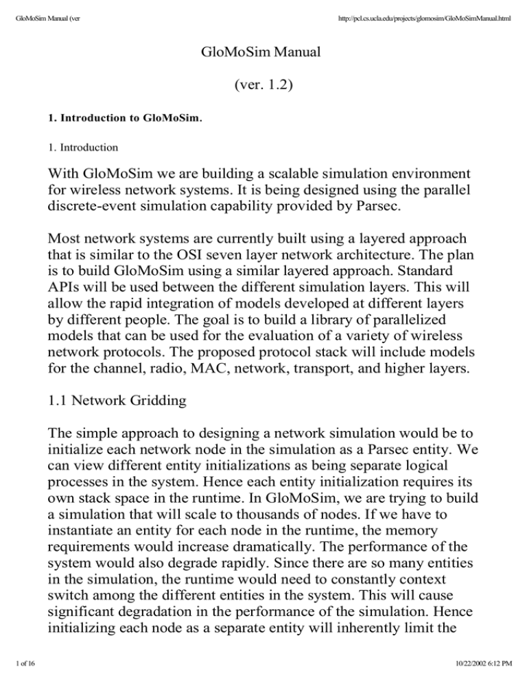
GloMoSim Manual (ver http://pcl.cs.ucla.edu/projects/glomosim/GloMoSimManual.html GloMoSim Manual (ver. 1.2) 1. Introduction to GloMoSim. 1. Introduction With GloMoSim we are building a scalable simulation environment for wireless network systems. It is being designed using the parallel discrete-event simulation capability provided by Parsec. Most network systems are currently built using a layered approach that is similar to the OSI seven layer network architecture. The plan is to build GloMoSim using a similar layered approach. Standard APIs will be used between the different simulation layers. This will allow the rapid integration of models developed at different layers by different people. The goal is to build a library of parallelized models that can be used for the evaluation of a variety of wireless network protocols. The proposed protocol stack will include models for the channel, radio, MAC, network, transport, and higher layers. 1.1 Network Gridding The simple approach to designing a network simulation would be to initialize each network node in the simulation as a Parsec entity. We can view different entity initializations as being separate logical processes in the system. Hence each entity initialization requires its own stack space in the runtime. In GloMoSim, we are trying to build a simulation that will scale to thousands of nodes. If we have to instantiate an entity for each node in the runtime, the memory requirements would increase dramatically. The performance of the system would also degrade rapidly. Since there are so many entities in the simulation, the runtime would need to constantly context switch among the different entities in the system. This will cause significant degradation in the performance of the simulation. Hence initializing each node as a separate entity will inherently limit the 1 of 16 10/22/2002 6:12 PM GloMoSim Manual (ver http://pcl.cs.ucla.edu/projects/glomosim/GloMoSimManual.html scalability and performance of the simulation. To circumvent these problems network gridding was introduced into the simulation. With network gridding, a single entity can simulate several network nodes in the system. A separate data structure representing the complete state of each node is maintained within the entity. Similarly we need to maintain the right level of abstraction. When the simulation code of a particular node is being executed it should not have access to the data structures of the other nodes in the simulation. The network gridding technique means that we can increase the number of nodes in the system while maintaining the same number of entities in the simulation. In fact, the only requirement is that we need only as many entities as the number of processors on which the simulation is being run. Hence if we are running a sequential simulation we need to initialize only one entity in the system. We also don't meet the memory or context switching problems that limit the simulation. In GloMoSim, each entity represents a geographical area of the simulation. Hence the network nodes which a particular entity represents are determined by the physical position of the nodes. Suppose we specify the following in the input file: # SIMULATION-RANGE-X 100 SIMULATION-RANGE-Y 100 # # Number of partitions in x and y range. PARTITION-NUM-X 2 PARTITION-NUM-Y 2 # We would now have a simulation are of size (100 * 100). We would also have 4 partitions (each partition is represented by a single entity) in the simulation. So one partition would encompass the 2 of 16 10/22/2002 6:12 PM GloMoSim Manual (ver http://pcl.cs.ucla.edu/projects/glomosim/GloMoSimManual.html square area represented by the coordinates (0, 0), (49, 0), (0, 49), and (49, 49). Note: The current distribution of GloMoSim only works with a single partition. Since each partition is a regular rectangular region, a partition can have at most eight neighboring partitions. Thus if a network node sends out a message, it has to be sent to at most eight other entities in the simulation. This is much easier then the simple design we talked about originally. If each entity is represented a single network node, broadcasting a message from a node becomes very difficult. The first option is that each entity would have to constantly keep track of the other entities that are within the power range. This becomes difficult if we want to introduce mobility of nodes in the simulation. The second option is that when a node sends out a message, it would be sent to all the other entities in the simulation. The receiving entity could then accept the message if its in the power range of the sender. This is also very inefficient as the number of nodes in the simulation increases. Hence a simple message transmission could become very complicated when we do not use network gridding. 1.2 Layered Structure Since we are building GloMoSim using a layered approach, we would like to have the ability to rapidly integrate models developed at different layers by different people. Hence the simple approach here would seem to be that each layer in the simulation would be represented by a different Parsec entity. We would still have the same problem that we had previously. As the number of layers in the simulation increases, the number of entities in the simulation would also increase. This would lead to scalability and performance problems in the simulation. But this is not as dramatic since there are only a few layers in the simulation. But there are other reasons why we need to aggregate the layers into a single entity. Often times, different layers of the simulation need to access certain 3 of 16 10/22/2002 6:12 PM GloMoSim Manual (ver http://pcl.cs.ucla.edu/projects/glomosim/GloMoSimManual.html common variables. For example, the upper layers of the simulation need to use the CPU when they are executing any instructions. But CPU is a shared resource among these layers. Hence, before executing any instructions a layer has to make sure that the CPU is free. Hence the upper layers need to have access to common variables which will provide information about the state of the CPU. If these layers are kept as different entities in the simulation we don't have a way of accessing shared variables. Besides we don't want to use any global variables as they can create problems for parallel execution. If the layers are kept as different entities, each layer also has to explicitly keep track of the "ename" value for the upper and lower layers. These "ename" values are needed for message passing among the various layers. For parallel conservative runtime, each entity also has to specify the source and destination set as well as the lookahead values for the entity. Specifying lookahead for an entity can become very complicated. All this creates additional work for the developer who is basically interested in modeling a particular network protocol. For these reasons, we decided to integrate the various GloMoSim layers into a single entity. Each entity now encompasses all the layers of a simulation. Instead each layer is now implemented as functions in the new design. We provide an initialization function that will be called for each layer of each node at the beginning of the simulation. We provide functions that can be used to send messages between the layers. When a layer receives a particular message, it will automatically invoke a function that is provided by the developer of that particular layer. And based on the contents of the message, the function can then execute the appropriate instructions. At the end of the simulation, a function is also called for each layer of each node. A layer can use this function to collect any relevant statistics. An actual implementation of a particular layer will be shown shortly. 4 of 16 10/22/2002 6:12 PM GloMoSim Manual (ver http://pcl.cs.ucla.edu/projects/glomosim/GloMoSimManual.html 2. Directory Structure of GloMoSim. After downloading and upzipping GloMoSim, it should contain the following directories: /applicaiton contains code for the application layer /bin for executable and input/output files /doc contains the documentation /include contains common include files /mac contains the code for the mac layer /main contains the basic framework design /network contains the code for the network layer /radio contains the code for the physical layer /transport contains the code for the transport layer You have to compile the files from the main/ directory. Run "make depend" to create list of depndencies in the Makefile. Make sure that the right path for the Parsec compiler is specified in the Makefile for the "PAR" variable. Run "make" to create the executable You can also use Makent.bat for compiling in batch mode (for NT). To run the simulation you have to go to the bin/ directory. The executable is called "Sim". It taked only one command line paramter, which is an input file. An example input file is CONFIG.IN in bin/ directory. Run "Sim CONFIG.IN" to run the program. A file called "GLOMO.STAT" is produced at the end of the simulation and contains all the statistics generated by the simulation. Make modifications to CONFIG.IN to vary the parameters for running the simulation. 3. Description of input file. This section explains the various parameters which are part of the input file supplied to the GloMoSim executable. In the input file 5 of 16 10/22/2002 6:12 PM GloMoSim Manual (ver http://pcl.cs.ucla.edu/projects/glomosim/GloMoSimManual.html anything following a "#" is treated as a comment. Note that some parameters presented in this section may not be valid in the latest GloMoSim library as we keep updating the library to be configured easily. The "config.in" file included in the distribution should be the most up-to-date configuration file and used as a template file. The following two parameters stand for the physical terrain in which the nodes are being simulated. For example, the following represents an area of size 100 meters by 100 meters. All range parameters are in terms of meters. # # Terrain Area we are simulating. TERRAIN-RANGE-X 100 TERRAIN-RANGE-Y 100 # The following parameter represents the power range of wireless nodes in the simulation. For example, a node can reach any other node within 50 meters of its position. # POWER-RANGE 50 # The following is a random number seed used to initialize part of the seed of various randomly generated numbers in the simulation. This can be used to vary the seed of the simulation to see the consistency of the results of the simulation. # SEED 1 # The following parameter represents the maximum simulation time. The numbered portion can be followed by optional letters to modify 6 of 16 10/22/2002 6:12 PM GloMoSim Manual (ver http://pcl.cs.ucla.edu/projects/glomosim/GloMoSimManual.html the simulation time. For example: 100NS - 100 nano-seconds 100MS - 100 milli-seconds 100S - 100 seconds 100 - 100 seconds (default case) 100M - 100 minutes 100H - 100 hours 100D - 100 days # SIMULATION-TIME 100M # The following parameter represents the number of nodes being simulated. # NUMBER-OF-NODES 12 # The following parameter represents the node placement strategy. - RANDOM: Nodes are placed randomly within the physical terrain. - UNIFORM: Based on the number of nodes in the simulation, the physical terrain is divided into a number of cells. Within each cell, a node is placed randomly. - GRID: Node placement starts at (0, 0) and are placed in grid format with each node GRID-UNIT away from its neighbors. The number of nodes has to be square of an integer. - FILE: Position of nodes is read from NODE-PLACEMENT-FILE. On each line of the file, the x 7 of 16 10/22/2002 6:12 PM GloMoSim Manual (ver http://pcl.cs.ucla.edu/projects/glomosim/GloMoSimManual.html and y position of a single node is separated by a space. #NODE-PLACEMENT RANDOM #NODE-PLACEMENT UNIFORM #NODE-PLACEMENT GRID #GRID-UNIT 30 #NODE-PLACEMENT FILE #NODE-PLACEMENT-FILE nodes.input # The propagation models used for determining if a node is reachable: - Free Space: Predicts received signal strength when the transmitter and receiver have a clear, unobstructed line-of-sight path between them. Received power decays as a function of the T-R separation distance. - Rayleigh Fading Distribution: The Rayleigh Fading Distribution is used to describe the statistical time varying nature of the received envelope of a flat fading signal, or the envelope of an individual multipath component. - Ricean Fading Distribution: When there is a dominant stationary (nonfading) signal component present, such as line-of-sight propagation path, the small-scale fading envelope distribution is Ricean. In such a situation, random multipath components arriving at different angles are superimposed on a stationary dominant signal. At the output of an envelope detector, this has the effect of adding a dc component to the random multipath. The effect of a dominant signal arriving with many weaker multipath signals gives rise to the Ricean distribution. As the dominant signal becomes weaker, the composite signal resembles a noise signal which has an envelope that is Rayleigh. Thus the Ricean distribution degenerates to a Rayleigh distribution when the dominant component fades away. The Ricean distribution is often described in terms of 8 of 16 10/22/2002 6:12 PM GloMoSim Manual (ver http://pcl.cs.ucla.edu/projects/glomosim/GloMoSimManual.html a parameter K which is defined as the ratio between the deterministic signal power and the variance of the multipath. It is given by: K = (A^2) / (2*sigma^2) or, in terms of dB: K(dB) = 10log((A^2)/(2*sigma^2)) (dB) The parameter K is known as the Ricean factor and completely specifies the Ricean distribution. As A->0, K->-infinity dB, and as the dominant path decreases in amplitude, the Ricean distribution degenerates to a Rayleigh distribution. The formulas for computing these 3 propagation models were taken from: "Wireless Communication", Chapters 3 & 4, by Theodore S. Rappaport. You can look there for more detailed information about these models. #PROPAGATION-FUNC FREE-SPACE #PROPAGATION-FUNC RAYLEIGH #PROPAGATION-FUNC RICEAN # # RICEAN-K-FACTOR only used for PROPAGATION-FUNC RICEAN # Ratio between deterministic signal power and the variance # of the multipath. (range: -5.0dB to 20.0dB) #RICEAN-K-FACTOR 6.0 # The following parameter represents the bandwidth (in bits per second) at which nodes will transmit messages. # BANDWIDTH 2000000 # For some layers of the simulation, there are multiple protocols built into the simulation. You can specify the protocol that you are interested in by commenting out the protocols that you are not interested in. For example for the radio layer, we have radio with 9 of 16 10/22/2002 6:12 PM GloMoSim Manual (ver http://pcl.cs.ucla.edu/projects/glomosim/GloMoSimManual.html and without capture ability. For the MAC layer we have protocols for CSMA, MACA, and IEEE802.11. For the routing protocol we have Bellmanford and OSPF. #RADIO-TYPE RADIO-NO-CAPTURE #RADIO-TYPE RADIO-CAPTURE #MAC-PROTOCOL CSMA #MAC-PROTOCOL MACA #MAC-PROTOCOL 802.11 # #ROUTING-PROTOCOL BELLMANFORD #ROUTING-PROTOCOL OSPF #NETWORK-PROTOCOL IP # For the transport layer there are various protocols which can be used individually or concurrently. If you are only interested in simulating a particular protocol, you can place a "NO" for other protocols you are no interested in. This will probably make your simulation a little faster. # TRANSPORT-PROTOCOL-TCP YES TRANSPORT-PROTOCOL-UDP YES # The following parameters determine if you are interested in the statistics of a single or multiple layer. By specifying the following parameters as YES, the simulation will provide you with statistics for that particular layer. All the statistics are compiled together into a file called "GLOMO.STAT" that is produced at the end of the simulation. If you need the statistics for a particular node or particular protocol, it is easy to do the filtering. Every single line in the file is of the following format: Node: 9, Layer: RadioNoCapture, Total number of collisions is 0 # TCP-STATISTICS NO 10 of 16 10/22/2002 6:12 PM GloMoSim Manual (ver http://pcl.cs.ucla.edu/projects/glomosim/GloMoSimManual.html UDP-STATISTICS NO ROUTING-STATISTICS NO NETWORK-LAYER-STATISTICS NO MAC-LAYER-STATISTICS NO RADIO-LAYER-STATISTICS YES CHANNEL-LAYER-STATISTICS NO # The following represent parameters for mobility. If MOBILITY is set to NO, than there is no movement of nodes in the model. For the RANDOM-DRUNKEN model, if a node is currently at position (x, y), it can possibly move to (x-1, y), (x+1, y), (x, y-1), and (x, y+1); as long as the new position is within the physical terrain. For random waypoint, a node randomly selects a destination from the physical terrain. It moves in the direction of the destination in a speed uniformly chosen between MOBILITY-WP-MIN-SPEED and MOBILITY-WP-MAX-SPEED (meter/sec). After it reaches its destination, the node stays there for MOBILITY-WP-PAUSE time period. The MOBILITY-POSITION-GRANULARITY (in meters) is used for GloMoSim to calculate the frequency of updating the position of each network node. MOBILITY NONE #Random Waypoint and its required parameters. #MOBILITY RANDOM-WAYPOINT #MOBILITY-WP-PAUSE 30S #MOBILITY-WP-MIN-SPEED 0 #MOBILITY-WP-MAX-SPEED 10 #MOBILITY TRACE #MOBILITY-TRACE-FILE ./mobility.in #MOBILITY REFERENCE-POINT-GROUP #MOBILITY BBN #MOBILITY PATHLOSS-MATRIX #MOBILITY RANDOM-DRUNKEN 11 of 16 10/22/2002 6:12 PM GloMoSim Manual (ver http://pcl.cs.ucla.edu/projects/glomosim/GloMoSimManual.html MOBILITY-POSITION-GRANULARITY 0.5 The following is used to setup applications such as FTP and Telnet. The file will need to contain parameters that will be use to determine connections and other characteristics of the particular application. # APP-CONFIG-FILE app.conf # The format of "app.conf" is the following: FTP <source> <dest> <items to send> <start time> TELNET <source> <dest> <session duration> <start time> Tcplib will choose a random value for the following if they are specified as 0: FTP: <items to send> TELNET: <session duration> 4. Statistics Collected by Layers in GloMoSim. 1 Radio Layer Statistics Total number of packets from mac Total number of packets from channel Total number of collisions Power consumed 2. MAC layer statistics 2.1 CSMA Number of packets from network Number of packets lost due to buffer overflow Number of UNICAST packets output to the channel Number of BROADCAST packets output to the channel Number of UNICAST packets received clearly Number of BROADCAST packets received clearly 12 of 16 10/22/2002 6:12 PM GloMoSim Manual (ver http://pcl.cs.ucla.edu/projects/glomosim/GloMoSimManual.html 2.2 MACA Number of packets from network Number of packets lost due to buffer overflow Number of UNICAST packets output to the channel Number of BROADCAST packets output to the channel Number of UNICAST packets received clearly Number of BROADCAST packets received clearly Number of RTS Packets sent Number of CTS Packets sent Number of RTS Packets got Number of CTS Packets got Number of Noisy Packets got 2.3 802.11 Number of packets from network Number of packets lost due to buffer overflow Number of UNICAST (non-fragmented) packets output to the channel Number of BROADCAST packets output to the channel Number of UNICAST packets received clearly Number of BROADCAST packets received clearly Number of retx packets due to CTS timeout Number of retx packets due to ACK timeout Number of retx packets due to FRAG ACK timeout Number of packets dropped due to exceeding retx timeout count Number of packets dropped due to exceeding frag. retx timeout count. 3. Network Layer Statistics 3.1 IP Number of pkts from TCP Number of pkts to TCP Number of pkts from UDP Number of pkts to UDP Number of pkts from OSPF Number of pkts to OSPF 13 of 16 10/22/2002 6:12 PM GloMoSim Manual (ver http://pcl.cs.ucla.edu/projects/glomosim/GloMoSimManual.html Number of TCP pkts dropped due to exceeding ttl or network unreachable Number of UDP pkts dropped due to exceeding ttl or network unreachable Number of OSPF pkt dropped due to exceeding ttl or network unreachable Average Number of hops TCP pkts traversed Average Number of hops UDP pkts traversed Average Number of hops OSPF pkts traversed 4. Transport Layer Statistics 4.1 TCP Total packets sent to network layer Data packets sent Data packets in sequence Data packets retransmitted Ack-only packets sent Pure control (SYN|FIN|RST) packets sent Window update-only packets sent Window probes sent Data packets received In sequence ack packets received Duplicate ack packets received Pure control (SYN|FIN|RST) packets received Window update-only packets received Window probes received Total packets with error Packets received with ccksum errs Packets received with bad offset Packets received too short 4.2 UDP Number of pkts from application Number of pkts to application 5. Application Layer Statistics 14 of 16 10/22/2002 6:12 PM GloMoSim Manual (ver http://pcl.cs.ucla.edu/projects/glomosim/GloMoSimManual.html 5.1 Routing Protocols 5.1.1 Bellmanford Total number of loop back packets Total number of routing table broadcasts Total number of triggered routing table updates Total number of routing table updates Total number of packets received from MAC Total number of packets received from Transport Layer Total number of packets sent Total number of packets belonging to this node Total hops traversed by own packets Total number of packets dropped Total number of packets dropped due to pass hop limit Total number of packets dropped due to no routing information 5.1.2 OSPF Number of Hello Packet Sent Number of Hello Packet Received Number of Times LSA Packet Originated Number of LSA Packet Retransmitted Number of LSA Packet Sent Total Number of LSA Packet Received Number of Link State Ack Packet Sent Number of Link State Ack Packet Received Number of Routing Table Updates 5.2 Traffic Generators 5.2.1 Ftp client and server Time when session is started Time when session is closed Number of bytes sent Number of bytes received Throughput. 15 of 16 10/22/2002 6:12 PM GloMoSim Manual (ver http://pcl.cs.ucla.edu/projects/glomosim/GloMoSimManual.html 5.2.2 Telnet client and server Time when session is started Time when session is closed Number of bytes sent Number of bytes received Throughput. 16 of 16 10/22/2002 6:12 PM
