Document 13469111
advertisement
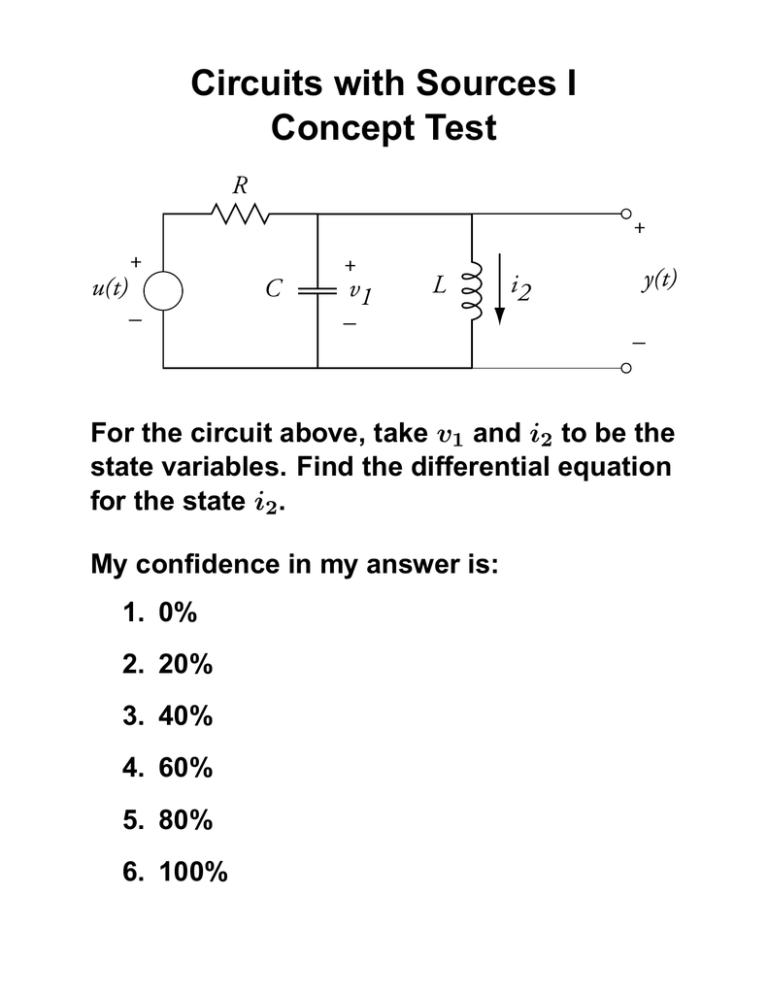
Circuits with Sources I Concept Test R + + u(t) C – + v1 – L i2 y(t) – For the circuit above, take v1 and i2 to be the state variables. Find the differential equation for the state i2 . My confidence in my answer is: 1. 0% 2. 20% 3. 40% 4. 60% 5. 80% 6. 100% Circuits with Sources I Concept Test R + + u(t) C – + v1 – L i2 y(t) – For the circuit above, take v1 and i2 to be the state variables. The differential equation for the state i2 is di2 dt = 1 L v1 My answer was 1. Completely correct. 2. Had one or two small errors. 3. Incorrect. 4. I didn’t understand the problem. Circuits with Sources I Solution Lecture S13: Circuits with Sources I (Confidence) 1 Answer 2 3 4 5 6 0 5 10 Number of Students 15 Lecture S13: Circuits with Sources I (Correctness) Answer 1 2 3 4 0 5 10 15 Number of Students 20 25 The differential equation for i2 is di2 1 = v2 dt L But v2 = v1 , since the inductor and capacitor are in parallel, and the voltage across the inductor is referenced the same way as the capactior. Therefore, di2 1 = v1 dt L Note that differential equation is in terms of states and parameters of the circuit only. The class had some difficulty with this problem. There should be plenty of practice on the problem set. Circuits with Sources II Concept Test R + + u(t) C – + v1 – L i2 y(t) – For the circuit above, take v1 and i2 to be the state variables. Find the differential equation for the state v1 . My confidence in my answer is: 1. 0% 2. 20% 3. 40% 4. 60% 5. 80% 6. 100% Circuits with Sources II Concept Test R + + u(t) + v1 – C – L y(t) i2 – For the circuit above, take v1 and i2 to be the state variables. The differential equation for the state v1 is dv1 dt =− 1 RC v1 − 1 C i2 (t) + 1 RC u(t) My answer was 1. Completely correct. 2. Had one or two small errors. 3. Incorrect. 4. I didn’t understand the problem. Circuits with Sources II Solution Lecture S13: Circuits with Sources II (Confidence) 1 Answer 2 3 4 5 6 0 5 10 15 20 Number of Students 25 30 Lecture S13: Circuits with Sources II (Correctness) Answer 1 2 3 4 0 5 10 15 Number of Students 20 25 The differential equation for v1 is 1 dv1 = i1 dt C So we need to solve for i1 . We can apply KCL to the node at the top of the capacitor to obtain i1 + v1 − u + i2 = 0 R Solving for i1 , i1 = − 1 1 v1 − i2 (t) + u(t) R R Therefore, 1 dv1 1 1 =− v1 − i2 (t) + u(t) RC C RC dt
