Refraction and Snell’s Law
advertisement
Refraction and Snell’s Law
Reading - Shen and Kong – Ch. 4
Outline
• TE and TM fields
• Refraction and Snell’s Law:
- From TE analysis
- From Phase Matching
- From Fermat’s Principle of Least Time
• Total Internal Reflection and Fibers
• FIOS
1
Image in the Public Domain
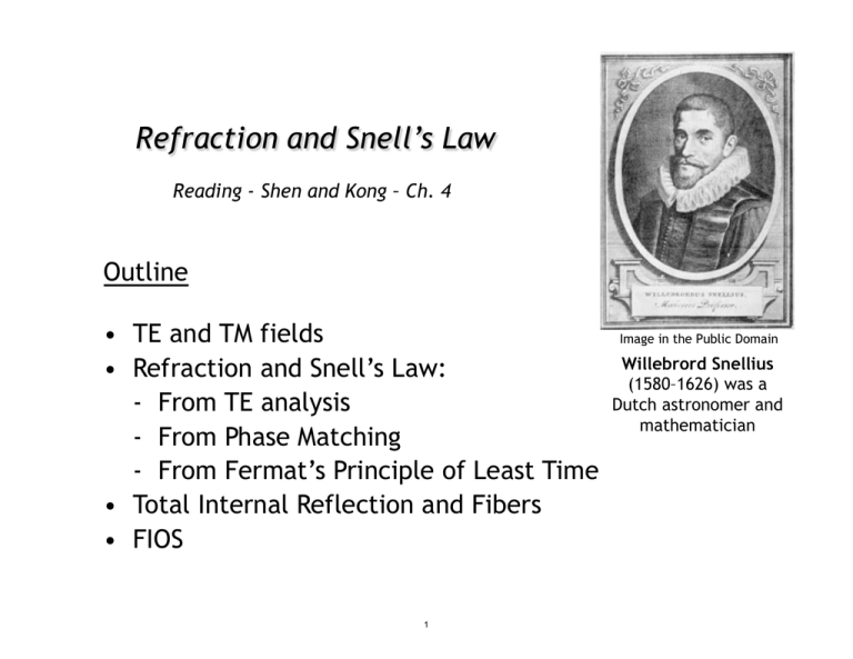
Willebrord Snellius
(1580–1626) was a
Dutch astronomer and
mathematician
Refraction
E&M Waves
Image by NOAA Photo library
http://www.flickr.com/photos/
noaaphotolib/5179052751/ on flickr
Water Waves
Waves refract at the top where
the water is shallower
Refraction involves a change in the direction of wave propagation
due to a change in propagation speed. It involves the oblique
incidence of waves on media boundaries, and hence wave
propagation in at least two dimensions.
2
Oblique Incidence at Dielectric Interface
Hr
Et
Er
Ht
Ei
Transverse
Electric Field
Hi
Hr
Et
Er
Transverse
Magnetic Field
Ht
Ei
Hi
y•
3
Partial TE Analysis
Hr
z=0
i = yE
ˆ oi e−jkix x−jkiz z
E
Et
Er
r = yE
ˆ or e−jkrx x+jkrz z
E
Ht
Ei
Hi
t = ŷE t e−jktx x−jktz z
E
o
ωi = ωr = ωt
y•
Tangential E must be continuous at the boundary z = 0 for all x and for t.
Eoi e−jkix + Eor e−jkrx x = Eot e−jktx x
This is possible if and only if kix = krx = ktx and ωi = ωr = ωt
The former condition is phase matching kix = krx = ktx
4
Snell’s Law
n1
n2
x
y•
z
kix = krx
kix = ktx
n1 sin θi = n1 sin θr
n1 sin θi = n2 sin θt
θ i = θr
SNELL’S LAW
5
Snells Law via Phase Matching
λ1
θi
L
λ2
θt
Following phase continuity, the phase-front separation L is common to both the
incident and transmitted, or refracted, waves.
L sin(θi ) = λ1 = vp1 (2π/ω)
L sin(θt ) = λ2 = vp2 (2π/ω)
sin(θ1 )/ sin(θ2 ) = vp1 /vp2 = n2 /n1
6
Snell’s Law Diagram
Tangential E field
is continuous …
Eoi e−jkix + Eor e−jkrx x = Eot e−jktx x
kx
kix = ktx
Radius = k2
ktx
θr
θt
θt
kz
kix
Radius = k1
k 1 < k2
7
n1 sin θi = n2 sin θt
Refraction in Suburbia
Think of refraction as a pair of wheels on an axle going from a
sidewalk onto grass. The wheel in the grass moves slower,
so the direction of the wheel pair changes.
Note that the wheels
move faster (longer space)
on the sidewalk, and slower
(shorter space) in the grass.
8
Snell’s Law and Lenses
Conjunctiva
Zonula
Retina
Aqueous humour
Fovea
Lens
Pupil
Optic nerve
Cornea
Iris
!
"
Bend
towards
normal
Bend
away from
normal
glass
9
Surface
Normal
History of Snell’s Law
• Snell’s Law describing refraction was first recorded by Ptolemy in 140 A.D
• First described by relationship by Snellius in 1621
• First explained in 1650 by Fermat’s principle of least time.
EXAMPLES:
B
A
P
B’
P’
R
R’
Q
FOCUSING OPTICAL SYSTEM
BEAM OF LIGHT IS OFFSET AS IT PASSES
THROUGH A TRANSPARENT BLOCK
To apparent sun
Atmosphere
Light from sky
Light path
To true sun
Earth
Hot road or sand
NEAR THE HORIZON, THE APPARENT SUN IS HIGHER
THAN THE TRUE SUN BY ABOUT ½ DEGREE
MIRAGE
10
Fermat’s Principle of Least Time
Fermat’s principle of minimum time argues that light will travel from
one point to another along a path that requires the minimum time.
Applied to Reflection
A
•
•
•
B
B’
Since it is straight, the blue path is the shortest path from A to B’. So, the blue path
is also the shortest reflecting path to B since it images the path to B’. For the blue
path, the incidence and reflection angles equal.
11
Fermat’s Principle of Least Time
Refraction
A •
sinθi /sinθt = vp1 /vp2 = n2 /n1
y1
L
y2
x1
The time
t
require for light to travel from A to B is given by
t=
From
x21
+
y12
v1
+
((L − x1 )2 + y22 )
v2
dt/dx1 = 0 , it follows that
x v
x2 v2
1 1
=
(x21 + y12 )
((L − x1 )2 + y22 )
12
• B
Total Internal Reflection
Beyond the critical angle, θc , a ray within the
higher index medium cannot escape at shallower
angles
n2 sinθ2 = n1 sinθ1 θc = sin−1 (n1 /n2 )
TOTAL INTERNAL REFLECTION
For glass, the critical internal angle is 42°
For water, it is 49°
Image is in the public domain
n1 = 1.0
n2 = 1.5
INCOMING RAY HUGS SURFACE
42°
13
Snells Law Diagram
Tangential E field is continuous … kix = ktx
Refraction
Total Internal Reflection
kx
kx
Radius = k2
ktx
θr
θt
θt
θc
kz
θc
kix
Radius = k1
k 1 < k2
k 1 > k2
14
θt
kz
Applications of Total Internal Reflection
Critical angle (diamond/air interface): sin-1(n2/n1) = sin-1(1/2.42) ~ 24°
Critical angle (glass/air interface) is:
~ 42°
Critical
Angle
Image by Steve Jurvetson
http://en.wikipedia.org/wiki/
File:Apollo_synthetic_diamond.jpg on Wikipedia
Diamonds sparkle as light bounces inside them
multiple times due to the high index of refraction
15
Total Internal Reflection in Suburbia
Moreover, this wheel analogy is mathematically
equivalent to the refraction phenomenon.
One can recover Snell’s law from it: n1 sin θ1 = n2 sin θ2 .
The upper wheel hits the sidewalk and starts to go faster, which turns the axle
until the upper wheel re-enters the grass and wheel pair goes straight again
16
Waveguide Transports Light Between Mirrors
Metal waveguides
Dielectric waveguides
So what kind of waveguide
are the optical fibers ?
Image by Dan Tentler http://www.flickr.com/
photos/vissago/4634464205/ on flickr
17
Optical Fibers
Light Propagating Through
A Multimode Optical Fiber
Single Mode Fiber Structure
Jacket
400 μm
cladding
core
Acceptance
angle
Index of
refraction
Cladding
125 μm
Input pulse
Core
8 μm
125 μm
200 μm
Step Index Fiber
50-100
μm
Graded Index Fiber
Modal dispersion is a
distortion mechanism
occurring in multimode
fibers and other
waveguides, in which
the signal is spread in
time because the
propagation velocity of
the optical signal is not
the same for all modes
125 μm
125 μm
10 μm
Buffer
250 μm
Singlemode Fiber
18
Fiber to the Home
Time Division Multiplexing
Small Businesses
2.4 Gbps shared by up to 128 users
Splitter
10-100 Mbps
service rates
ONT
Splitter
2
3
ONT
ONT
ONT
2.4 Gbps out
1.2 Gbps in
1
2
OLT
3
4
20 km reach
Splitter
ONT
ONT
ONT
1
4
(located in Verizon's
central switching office)
Splitter
ONT
An ONT (Optical Network Terminal) is a media converter that is installed by Verizon
either outside or inside your premises, during FiOS installation. The ONT converts
fiber-optic light signals to copper/electric signals. Three wavelengths of light are
used between the ONT and the OLT (Optical Line Terminal):
• λ = 1310 nm voice/data transmit
• λ = 1490 nm voice/data receive
• λ = 1550 nm video receive
Each ONT is capable of delivering:
Multiple POTS (plain old telephone service) lines, Internet data, Video
19
Image by Raj from Chennai, India
http://commons.wikimedia.org/
wiki/File:Strings_of_lights.jpg
on Wikimedia Commons
Fiber to the Home
Image by uuzinger
http://www.flickr.com/photos/uuzinger/
411425461/ on flickr
Image by uuzinger
http://www.flickr.com/photos/uuzinger/
411425452/on flickr
POTS
Bandwidths & Services
Upstream
Downstream
1310 nm 1490 nm
Voice and
Data
Voice and
Data
ONT
Data
1550 nm
Video
ONT
Video
Channels downstream to each home
λ = 1490 and λ = 1550 nm
Channel upstream from each home
λ = 1310 nm
Power &
Battery
Image of ONT by Josh Bancroft
http://www.flickr.com/photos/joshb/87167324/ on flickr
20
Passive Optical Network (PON)
Optical Assembly
TO Can Laser
TO Can PINS
Single mode
fiber
Ball lens
Thin film filters
Upstream
Transmission
Channels downstream to each home
λ = 1490 and λ = 1550 nm
Downstream
Channelλupstream from each home
λ = 1310 nm
1310
1490 1550
Wavelength (nm)
21
Separating Wavelengths
Dispersion
Diffraction
Image by Ian Mackenzie
http://www.flickr.com/photos/
madmack/136237003/
on flickr
Sunlight diffracted through a 20 μm slit
Image is in the public domain
Image by wonker
http://www.flickr.com/photos/wonker/
2505350820/ on flickr
22
Fabry-Perot Resonance
Transmission
|t|
2
t12 t21 e−jkL
t=
1 − r12 r21 e−2jkL
1
0.8
0.6
0.4
0.2
0
1.5
1.52
1.54
1.56
1.58
Wavelength [μm]
Fabry-Perot Resonance:
max{e−2jk2 L } = 1
maximum transmission
min{e−2jk2 L } = −1
minimum transmission
23
Flexible Membrane
General concept of a
MEMS Fabry-Perot filter
formed on a detector
Membrane
Support
Top Mirror
(by applying voltage between the top
and bottom mirror the distance L
between the mirrors can be adjusted)
Bottom Mirror
Silicon
Readout
Detector
General concept of a
Mach-Zehnder Modulator
Phase Shifter
Light out
(phase shifters change the phase of the
light beam in one of the waveguide
arms with respect to the other beam,
so that they can constructively or
Light in
destructively interfere)
Phase Shifter
24
MIT OpenCourseWare
http://ocw.mit.edu
6.007 Electromagnetic Energy: From Motors to Lasers
Spring 2011
For information about citing these materials or our Terms of Use, visit: http://ocw.mit.edu/terms.
25
