Document 13405371
advertisement
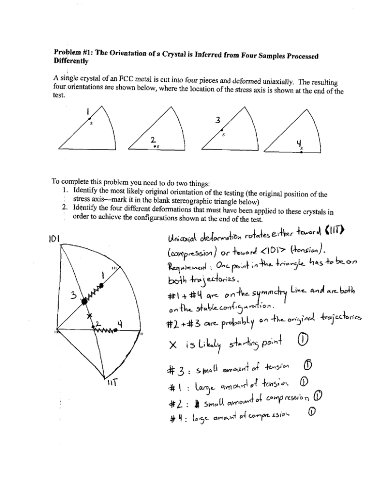
Problem #I: The Orientation of a Crystal is Inferred from Pour Samples Processed
Differently
A single crystal of an FCC metal is cut into four pieces and deformed uniaxially The resulting
four orientations are shown below, where the location of the stress axis is shown at the end of the
test.
To complete this problem you need to do two things:
Identify the most likely original orientation of the testing (the original position ofthe
1 stress axis-mark
it in the blank stereographic triangle below)
Identify the four different deformations that must have been applied to these crystals in
order to achieve the configurations shown at the end of the test,
2.
10I
un;n>ia(
&e&wa4ibb
( m w p - s i 1~ w +em ,.J 410.i~
(~sim).
l.q*k-rl O . i l a : ~;.r,me.
5L b * s + ~ h o ~
I
43
#\
sMkU
:
0
3en5iM
0
-tosI'* 0
csw rrsslbT, B
~~~.~irnrna+'o'
P
Ia3r orn~~l-4
dwwpsSioiO
J,4
: L u c y qwoh
* i
+Y
t .C
rn"3lw.n
Problem #2: Lock, Stock, and a Barrel Full of Partials
Consider two dislocations moving on different { I l l ) planes in an FCC crystal, which are
coming together at the same position as shown.
The two initial dislocations have Burgers vectors of a/2<110> type as shown; however, as the
picture implies, these dislocations are actually separated into partials of a/6<211> type.
Part A:
Write out the correct Burgers vectors for the four partials in this problem (not just familiesmake sure all the signs and order of the digits hkl are correct, and make sure that they lie in the
slip plane).
Part B:
Draw a picture showing the dislocation reaction that will occur when these dislocations meet.
Will the reaction lead to a sessile or a glissile configuration?
Problem 3: Twinning
In class we analyzed twinning in HCP metals quite thoroughly. We mentioned that twinning can
happen in FCC metals, although it is not as common. In fact, we discussed the fact that in FCC
crystals, the twinning plane is (1 1I), and the twinning direction is (1 12) .
Part A:
Twinning involves two undistorted planes. The second undistorted plane is
first undistorted plane?
'1.
What is the
Part B:
Knowing the twinning planes and twinning direction, do a simple calculation to determine the
amount of shear strain that would be produced by a twin. (Hint: you may want to draw some
pictures of the unit cell in order to get a feeling for the orientation of these planes and directions
with respect to one another)
,=\m-wO
y=-* (e-96*j*Z1
Part C:
0
-
.L c
4o0
Do you think that twinning would have a sign dependence to it in an FCC crystal? In other
words, will a positive stress cause twinning, but a negative stress not cause it (or vice versa)?
Explain your thinking.
Problem #4: Post-UROP Forensics
Working in an MIT lab, you are studying deformation and annealing of single crystals. You
have three identical specimens of the same metal, but which are cut with different crystal
orientations. You carefully perform tensile tests to a fixed level of strain, and then unload them.
You find:
stress
stress
Specimen A
strain
Specimen B
strain
Specimen C
strain
Now
take the three specimens and give them to your UROP, with the request that they all be
annealed at the same temperature for the same amount of time. Your UROP dutifully follows
your orders, but manages to forget which sample is which! Looking for clues to sort out this
mess, you perform metallography to look at the microstructure. Here is what you see:
Structure I
Structure I1
Structure 111
Sort out which post-annealing microstructure belongs to which sample, and write a short
explanation for your choices.
Problem 5: Annealing in Stereo
Below are five stereographic projections presented in the external reference frame. These
projections show the distribution of crystal orientations in different samples of an HCP metal.
The points represent the orientations of thec-axis (0001) of the crystals.
Which of these projections corresponds to each of the following situations? Provide one
sentence of explanation for each answer, please.
a. A single crystal is bent and then annealed lightly
> m e m y o T a r n C sign +poLy3m*.
5*nsl\m,,Dncm3q?icn
r
i* 0
~ U ~ Dk
5C,$+
b w A ; - ~ dl
P 7
-2 9
a n
b. A single crystal is deformed slightly in compression and annealed lightly
t
bLit
I0 4w a n ?
D&wl.t*\;a-
55h5
rnc*
J
odm-hi,bn,
7
sx
n u ? m,31h1
kxrs 5
Y
c. A single crystal is deformed slightly in compression and annealed thoroughly
,.h ;~4-?-
->
5%->
I
d. A single crystal is deformed heavily in compression and annealed
0
e. The sample from 'd' above is again deformed heavily and annealed
+ kL.
s ~ , , US~m . n ~ w o e 5x**i
m r t4om o*c-kj,oni
I
-b
3
Problem 6: In Which We Consider the Interaction Among Non-Parallel Dislocations,
Including Those That are Crossed and Those That Form Intriguing Loop Configurations
In class we dealt with the stress-field interactions between parallel dislocations only; we did not
talk about whether dislocations feel each other in other configurations. Based on your
understanding of dislocation stress fields, indicate whether the interaction in the following cases
would be attractive, repulsive, or non-existent. In each picture below, the Burgers vectors are
shown as arrows
Case A: Two screw dislocations separated by a distance Ax, at 90' from one another. (The
picture is drawn in perspective; the dislocations are parallel to the y and z axes)
""X
Case B: Two edge dislocatlo s separated by a distance Ax, at 90' from one another. (The picture
is drawn in perspective; the dislocations are parallel to the y and z axes)
7
-7,
y73
GX*
Case C: An edge and a screw dislocation separated
(The
is drawn in perspective; the dislocations are parallel to the y and z axes)
lsyy
~pulri~
sL-
in the plane of the loop, and
one with it normal to the loop.
i",LL4i-
Helpful (?) Bonus Information
Stress field around an edge dislocation:
all other 0 components are = 0.
Stress field around a screw dislocation:
all other 0 components are = 0, and note that rZ= xZ+$
Forces between dislocations:
Parallel edge:
Parallel screw:
JMAK Equation:
f = 1-exp(-kvdtd+l )
001
014
013
014
012
023
012
023
113
011
013
104
103
114
113
123
114
113 123
011
102
213 112
032
133
213 203
122
132
101
021
313
212
021
132
212
111
111
313 302
121
031
031
121
312
312
131
131
201
221
211
041
041
211
231
221
141
141
231
311 301
401 311
331 321
321 331
110 120 140
140 120 110
210 410 100 410 210
010
010
310
320
230 130
130 230
320 310
321
311
331
331
301
231
231
311
141
211
321
141
221
041
201
221
041
211 312
131
131
312
302
031
121
031
121
111 313 101 212
111
132
132
021
212
313
021
122
122
213 203
133
032
032
213 112
112
133
102
113
113 123
103
123
011
011
114 104 114
023
023
012
012
013
013 014
014
001
133
122
032
112
Figure by MIT OpenCourseWare.
112
123
213
011
101
113
114
023
132
012
013
331
221
121
104
014
123
203
102
313
103
001 114 113
213
312
212
211
112
311
113 114 104
014
112
411
103 114 013
141
111
123 111
213
231
321
012
212
102
113
221
023
221
122
313 203
112
331
133
331
312
123
213
011 132
101
321
313
121
211
133
231
212
032
302
122
201 312
110
111 132 021
110
131
311
320
031
301
121
411 401
211 221
131
041 141
230
310
311
141
410
120
140
411 321 331 231
210
130
310 320 110 120 140
100
010
410
141
411
231
321
230 130
210
131
411
141 041
411
321 331
401
231
311
311
131
031
301
121
211
221
211
121
021
201
131
312
302
101
312
212
313
213
111
114
132
221
113
112
032
132
331
011
123
Figure by MIT OpenCourseWare.
MIT OpenCourseWare
http://ocw.mit.edu
3.40J / 22.71J / 3.14 Physical Metallurgy
Fall 2009
For information about citing these materials or our Terms of Use, visit: http://ocw.mit.edu/terms .
