Session 4.2 ITU Seminar
advertisement

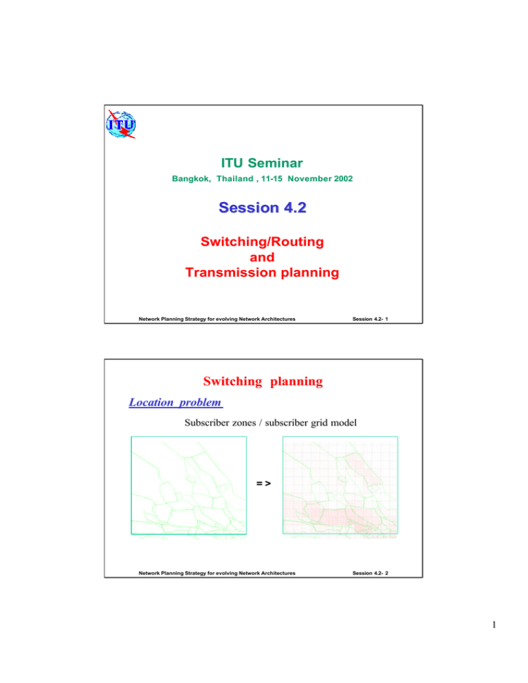
ITU Seminar Bangkok, Thailand , 11 11--15 November 2002 Session 4.2 Switching/Routing and Transmission planning Network Planning Strategy for evolving Network Architectures Session 4.2- 1 Switching planning Location problem Subscriber zones / subscriber grid model => Network Planning Strategy for evolving Network Architectures Session 4.2- 2 1 Switching planning Location problem Theoretically for the set of optimal location (XE,YE) the partial derivatives of the total network ∂C ∂X = 0 E cost function, C, with regard to for E = 1,2, K NEX ∂C ∂ YE = 0 XE and YE are equal to zero : Different methods for solving this 2*E equation system could be employed depending upon the methods of measuring the distances in the network In the most complicated case we get a system of 2*NEX non-linear equations If ∂C ∂X E and ∂C ∂ YE are expanded into Taylor-series this leads to a system of 2*NEX linear equations in ∆X F and ∆YF , which can easily be solved by standard methods Network Planning Strategy for evolving Network Architectures Session 4.2- 3 Switching planning Location problem - distance measurement methods Mean distance from exchange to grid element : (x 2 , y2 ) The mean distance from to the rectangle can then be found from: (x, y) Ly (X E ,YE ) D= (x1 , y1 ) 1 area x2 y2 ∫ ∫ d ( X E ,YE , x , y ) dx dy x1 y1 Lx (XE , YE ) along the hypotenuse : along the cathetie : D ( X E , Y E , x, y ) = X E − x + Y E − y D( X E ,YE , x , y ) = ( X E − x ) 2 ⋅ L2x + ( YE − y ) 2 ⋅ L2y Network Planning Strategy for evolving Network Architectures Session 4.2- 4 2 Switching planning Simplified method for location optimization S j = ∑ sub( i , j ) ⋅ Cs( DE ) Based on the access network cost S j only : for ( i , j ) ∈ E i For optimal locations (XE ,YE ) the partial derivatives of the cost function C= Sj with regard to XE and YE are equal to zero : For a case with one location only for XE we get: ∂ C ∂X E = ∂C ∂X E = 0 ∂C ∂YE = 0 ∑ [sub(i, j) ⋅ C ( D c ( i , j )∈E E for E = 1,2,K NEX ) ⋅ ∂DE ∂X E ] the partial derivative depends only on the distance Network Planning Strategy for evolving Network Architectures Session 4.2- 5 Switching planning Simplified method for location optimization With simplified distance method along the cathetie : ∂C ∂X E = We get : Thus : Or : D ( X E , YE , i, j) = X E − j + YE − i − 1 if j ≥ X E sub(i , j ) ⋅ Cc ( DE ) ⋅ i , j ∈E 1 if X E ≥ j ∑ ( ) ∑ sub(i , j ) ⋅ C (D c (i , j )< X ∑ sub(i , j ) ⋅ C ( D (i , j )<X c Finally if disregard the tr. media cost (same everywhere) we get: E )= E ).(+ 1) + ∑ sub(i, j ) ⋅ C ( D ∑ sub( i, j ) ⋅ C ( D c (i , j )> X c ( i, j )> X E E ).(−1) = 0 ) ∑ sub (i, j ) =( ∑) sub(i , j ) (i , j )< X Network Planning Strategy for evolving Network Architectures i,j >X Session 4.2- 6 3 Switching planning Location problem Graph model (subscribers in nodes) => Network Planning Strategy for evolving Network Architectures Session 4.2- 7 Switching planning Location problem - graph model Graph model presents network nodes and links connecting these nodes - cost function, C, is a discrete function over all node locations, i.e. it is not possible to use partial derivatives of C Obvious solution is to calculate the total network cost, C, for all combinations (solutions) and find the smallest C = Cmin Distances calculation as distances on graph – shortest path problem and corresponding algorithms For n nodes and N equipment items n! cost combinations (n-N)! N! Network Planning Strategy for evolving Network Architectures Session 4.2- 8 4 Switching planning Location problem - graph model Check all combinations - for very small networks pointless to investigate many of the combinations Heuristic methods - eliminate the obvious senseless combinations and investigate only some of the combinations Probabilistic methods for location optimization simulated annealing / simulated allocation Network Planning Strategy for evolving Network Architectures Session 4.2- 9 Switching planning Boundaries problem grid model graph model Network Planning Strategy for evolving Network Architectures Session 4.2- 10 5 Switching planning Boundaries problem Boundary optimization is finding service/exchange area boundaries in such a way that total network costs is minimized The cost of connecting one subscriber at location (x,y), belonging to traffic zone K, to an exchange/node E at ( X E ,YE ) can thus be expressed as : C ( E ) = C j ( K , E ) + Cb ( E ) + DE ⋅ C s ( DE ) + C f It depends of the cost of connecting the subscriber, the average exchange cost per subscriber, the backbone network cost of any subscriber The decision for the boundary can be made simply by comparison for every grid/node element (i,j) – the value C(E) is calculated for every exchange /node E and the lowest C(E) then determines E Network Planning Strategy for evolving Network Architectures Session 4.2- 11 Routing planning transiting of traffic High-usage route – part of the traffic is carried on the direct route and the rest of the traffic overflows through a tandem Direct routing 5 3 hierarchical network 4 high-usage routes Optimum final routes 1 2 Dual homing (load sharing) C(N) alternative routes NOPT Primary routes with Poisson-type offered traffic Network Planning Strategy for evolving Network Architectures ND N Circuits Session 4.2- 12 6 Routing planning Dual homing (load sharing) overflowing traffic is divided with predefined coefficient α Disjoint Routing Problem of Virtual Private Networks (VPN) – demands must be routed through a network so that their paths do not share common nodes or links VN VT SF-A Combinatorial optimization SZ methods for non-hierarchical routing optimize routing and simultaneously optimally dimension link capacities Network Planning Strategy for evolving Network Architectures disjoint routing Session 4.2- 13 Transmission planning Based on circuit/bandwidth matrix and transmission node/link data Network Planning Strategy for evolving Network Architectures Session 4.2- 14 7 Transmission planning Optimization of ring/mesh protected transport networks Two types of nodes could be distinguished in the network : § traffic access nodes – represent the abstract traffic entry points (e.g. local exchange) § transmission nodes – represent the actual network nodes (e.g. ADMs or DXCs ) Requirements to the topology for protection Ø ring or mesh topologies, multi-ring structures, hybrid ring-mesh topologies Ø different protection schemes: path protection, link protection, path diversity In the optimization methods are solved combinatorial problems usually with heuristic algorithms and based on the shortest path approach Network Planning Strategy for evolving Network Architectures Session 4.2- 15 Transmission planning Shortest path problem B 9 6 8 E H 4 5 J 10 A 7 7 10 11 9 v to determine the minimum cost path between two nodes G 6 6 v to determine the “shortest path” between any two nodes as minimum distance D 5 5 C Network Planning Strategy for evolving Network Architectures 6 F I Session 4.2- 16 8 Transmission planning Ø examine the adjacent nodes and label each one with its distance from the source node Shortest path problem – algorithm of Dantzig Ø examine nodes adjacent to those already labeled; when a node has links to two or more labeled nodes, its distance from each node is added to the label of that node; the smallest sum is chosen and used as the label for the new node Ø repeat above until either the destination node is reached (if the shortest route to only one node is required) or until all nodes have been labeled (if the shortest routes to all nodes are required) Network Planning Strategy for evolving Network Architectures Session 4.2- 17 Transmission planning Shortest path problem ü shortest path from A to J ü all partial paths contained in the path from A to J-(ABEHJ): (AB), (ABE), (ABEH), (BE), (BEH), (BEHJ), (EH), (EHJ), (HJ) are optimal paths, e.g. from B to J, the optimal path is (BEHJ) ü every optimal path consists of partially optimal paths Network Planning Strategy for evolving Network Architectures Session 4.2- 18 9 Switching planning Example boundaries v Grid element with 271 subscribers on a distance of 10 steps to upper exch. and 11 lo lower exch. – attach to service area of upper exch. v Grid element with 86 subscribers on a distance of 11 steps to upper exch. and 10 lo lower exch. – attach to service area of lower exch. v Boundary between grid elements 271 and 86 Network Planning Strategy for evolving Network Architectures Session 4.2- 19 Switching planning Example locations Optimum location according to the simplified method is the median of the accumulated subscribers sum – 4033 is within row 5 (Y=R5) Network Planning Strategy for evolving Network Architectures Session 4.2- 20 10


