Undersizing Preventers
advertisement

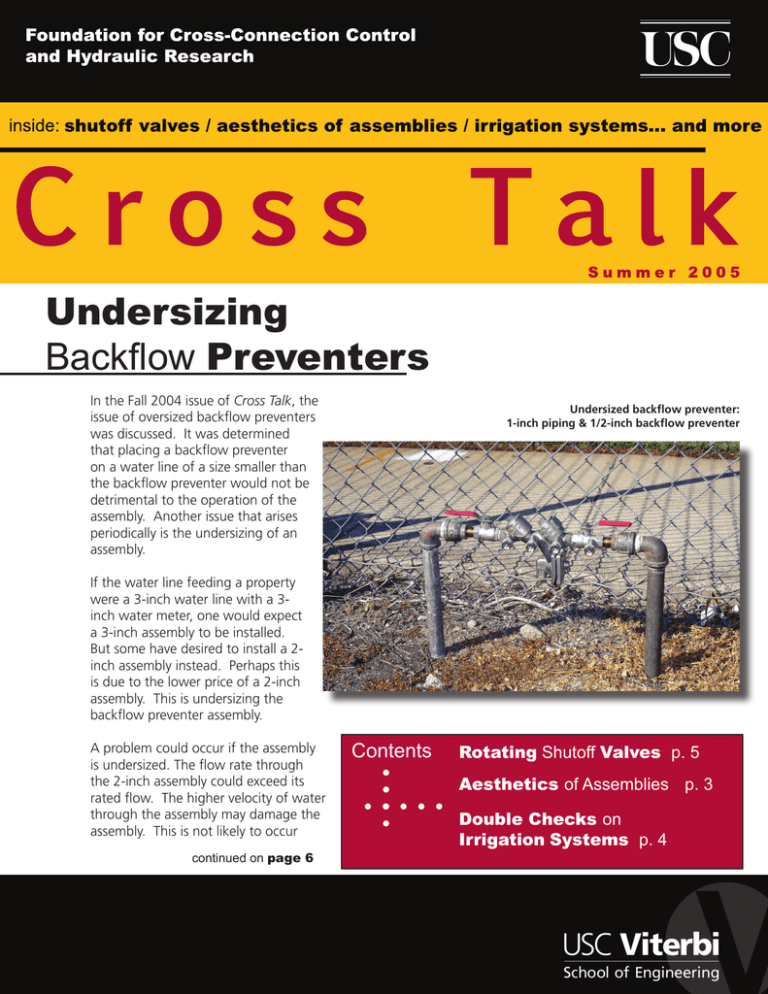
Undersizing Backflow Preventers In the Fall 2004 issue of Cross Talk, the issue of oversized backflow preventers was discussed. It was determined that placing a backflow preventer on a water line of a size smaller than the backflow preventer would not be detrimental to the operation of the assembly. Another issue that arises periodically is the undersizing of an assembly. Undersized backflow preventer: 1-inch piping & 1/2-inch backflow preventer If the water line feeding a property were a 3-inch water line with a 3inch water meter, one would expect a 3-inch assembly to be installed. But some have desired to install a 2inch assembly instead. Perhaps this is due to the lower price of a 2-inch assembly. This is undersizing the backflow preventer assembly. A problem could occur if the assembly is undersized. The flow rate through the 2-inch assembly could exceed its rated flow. The higher velocity of water through the assembly may damage the assembly. This is not likely to occur continued on page 6 Contents Rotating Shutoff Valves p. 5 Aesthetics of Assemblies p. 3 Double Checks on Irrigation Systems p. 4 Foundation Membership The Foundation’s Membership Program provides many benefits to the Members of the Foundation. These include: a twenty-five percent discount on manuals, twenty percent discount on Foundation Training Courses for any employee of the Member company/organization, the List of Approved Backflow Prevention Assemblies, printed quarterly, and access to the up-to-the-minute version of the List for those Members with Internet access. Members are encouraged to call the Foundation with technical questions. The Foundation’s Engineering Staff is available to assist members with the various aspects of field testing backflow preventers, installing backflow preventers and administering their crossconnection control program. Many consider their Membership with the Foundation one of their best forms of insurance to protect the agency from liability involved when a distribution system becomes contaminated or polluted through cross-connections. Membership in the Foundation helps to provide the tools needed to effectively initiate and run a cross-connection control program. Below is a list of those who have become Members of the Foundation this past quarter: Alamo Heights, City of Lubbock, City of Albeco Inc. McCloud C.S.D. Apex, Town of Memphis Light, Gas and Water Aylworth Fire Protection Miller Management BTE Mr. Backflow Inc. CCC Advisory Comm of San Diego County Parksville, City of EBA Engineering Parsons JPH Engineering Slayden Plumbing & Heating JTS Engineering Consultants, Inc. Southern Nevada Backflow Services K/C Engineering Stephanie Morgan Ken Fuglee & Associates, Inc. Stuart Grittman Kentucky American Water T&S Brass and Bronze Works Kevin Shaw Plumbing, Inc. Tract 180 Water Company Lathrop, City of Cross Talk is published by the Foundation for Cross-Connection Control and Hydraulic Research at the University of Southern California for Foundation Members. Limited additional copies are available to Members upon request. 2005 © University of Southern California. All rights reserved. Cross Talk SUMMER 2005 Page 2 Aesthetics of Backflow Prevention Assemblies Maintaining a backflow preventer hidden from public view can be a difficult task. Protecting the assembly from being tampered with or vandalized is a concern that any administrative authority must think about when decisions are being made regarding the installation of an assembly. In addition, public Example 1 (FRONT) From across the street the backflow preventer is successfully hidden from view. safety issues can occur like obstructing pedestrian traffic or restricting access to the handicapped. It doesn’t take much walking around a downtown district or neighborhood to bump into a backflow preventer. It’s not only important that these assemblies be hidden for aesthetic purposes but also to prevent the assembly from being tinkered with. Cities around the country have taken different approaches to camouflaging the assemblies. For example, some cities have taken an artistic approach to hiding the assemblies from view. The city places utility boxes on top of backflow preventers and then encourages local artists to paint on them to camouflage the plain enclosures. This approach not only prevents anyone unauthorized from tinkering with the assembly, but also adds a bit of flare to the neighborhood atmosphere. In warm weather climates backflow preventers are installed close to water meters, which typically are located at the edge of the sidewalk or property line. Example 1 (BACK) Although hidden from view the backflow preventer is still accessible for testing and maintenance. Where freezing conditions exist, placement inside a building is more common. For the administrative authority, it’s important to take into account any traffic whatsoever; limiting the amount of traffic can decrease the chances of the assembly being tampered with and in the long run avoid any difficult situations. Other modes of camouflaging backflow preventers involve hiding it by limited landscaping that can include small trees, brush or inside grass shacks. Other installers use artificial rocks with hollow insides to hide the assemblies from public view. What looks like an ordinary rock at times can actually be a backflow preventer enclosure. continued on page 7 Cross Talk SUMMER 2005 Page 3 Double Checks on Irrigation Systems Double check valve assemblies have a specific use in cross-connection control, as does every type of backflow prevention assembly. The type of assembly used in any situation must depend upon the hydraulic condition and the degree of hazard of the substance against which the assembly is protecting. The double check valve assembly may be used to protect against a backpressure situation. The assembly consists of two internally loaded check valves; backpressure pressing against the backside of a properly operating No. 2 check valve will be stopped. Should the No. 2 check valve leak, the No. 1 check valve will prevent backflow from occurring, not allowing any downstream pollutants into the upstream potable water supply. Check valves do, on occasion, become fouled by debris in the water. It is possible for one or both of the check valves in a double check valve assembly to become fouled. If only one of the check valves becomes fouled the other check valve will still protect the upstream potable water. If, however, both check valves become fouled, a more serious problem may occur. Polluted water from downstream of the assembly may flow to the upstream side of the assembly should either backpressure or backsiphonage occur through the leaking check valves. Although it is not common for both check valves in a double check valve assembly to become fouled, it is certainly possible. This is the reason that the double check valve assembly was never intended to be used to protect against a health hazard. The standard for check valve assemblies was written with the thought that these assemblies would only be used to protect against a pollutant. (We use the term pollutant to mean a non-health hazard; a substance, which may be aesthetically objectionable, but will not cause illness or death.) In some areas the administrative authority has accepted the installation of double check valve assemblies on irrigation systems. When one thinks of an irrigation system, one may not think of a system with fertilizer or chemical injectors. Thus the thought of using a double check valve assembly may seem appropriate; however, it should be noted that irrigation systems are to be considered a contaminant or a health hazard. Even if there is no fertilizer or chemical injection, water may pool around sprinkler heads. This would certainly be considered a health hazard because there is no control of the quality of water pooling around the sprinkler head. Fertilizer or chemicals may be hand broadcast onto a lawn or an area being irrigated. This would certainly degrade the quality of any water pooling near the sprinkler head. Additionally, there is a good chance there is residue from animal deposits on the lawn contaminating the water. The main point is that any water pooling in an open area is subject to contamination from a variety of sources, therefore an irrigation system should always be considered a health hazard. A double check valve assembly should never be used on an irrigation system. Some have allowed double check valve assemblies to be used on irrigation systems because they believe they can protect a double check valve assembly from freezing by installing it below grade, whereas this is not Cross Talk SUMMER 2005 Page 4 Foundation Notes acceptable with a reduced pressure principle assembly, pressure vacuum breaker, spill-resistent vacuum breaker or atmospheric vacuum breaker. Rotating Shutoff Valves The Foundation would like to recommend that all backflow prevention assemblies be installed above grade. There have been instances where double check valve assemblies have been installed below grade to prevent freezing and they have ended up completely under water due to a flooded vault. In other cases they have become completely buried because of mud filling in the vault during a rainy season. The Foundation often receives inquiries about rotating flanged shutoff valves. Installers or inspectors may want to rotate the shutoff valve (i.e. NRS or OS&Y Gate Valves) of some assembly in order to get it to fit into a specific area or to provide better access to the shutoff valve. The general response is that assemblies need to be installed in the orientation under which they were approved. It is true, however, the Foundation has determined that it is possible to rotate flanged shutoff valves of the 2.5inch size and larger one bolt hole. This will not affect the operation of the assembly, the shutoff valve, nor will it affect the approval of the assembly. Once a double check valve assembly is submerged in water in a vault, a cross-connection has actually been created between the test cocks and the water in the vault. Again, there is no control of the quality of the water in the vault. Therefore, a backflow preventer which was installed to prevent backflow from a non-health hazard from occurring, could actually become the source of a cross-connection with a contaminant because of its submerged test cocks. This only affects the flanged 2.5-inch and larger assemblies and it is important that the assembly be installed in the orientation under which it was approved. The Foundation urges its members to install all backflow preventers above grade. If a double check must be installed below grade, please make sure that adequate drainage has been provided. Cross Talk SUMMER 2005 Page 5 Undersizing Backflow Preventers continued from page 1 if the size of all the piping downstream of the assembly is 2-inches or less. However, a 3-inch meter would indicate that the prop- erty owner expects to use up to 320 gallons per minute, which is the rated flow of a 3-inch water meter (i.e. AWWA Std. C702 Compound Meters) and a 3-inch backflow preventer (Table 10-1 Manual of Cross-Connection, 9th Edition). A 2-inch backflow preventer and 2-inch water meter are both rated at 160 GPM—half the rating of the 3-inch size. If a 2-inch assembly was installed on a 3-inch line with a 3-inch water meter and the water usage was in excess of the rated flow of 160 GPM, damage may be caused to the backflow preventer because of the high velocity of water which would be flowing through the assembly. Although any flow rate between 160 GPM and 320 GPM would fall within the operating parameters of the meter, this flow would exceed the parameters of the backflow preventer. A good policy and one enforced in most jurisdictions, is to install a backflow preventer of the same size as the water meter. This will prevent the possibility of damage to the backflow preventer due to undersizing. The Foundation’s recommendation, in general, would be to install a backflow preventer which is sized the same as the water meter. However, it is noted that oversizing a backflow preventer should not be detrimental to the operation of the backflow preventer. Foundation Research Projects Research on Transient Flow Computer simulation and experimental study has been conducted at the Foundation laboratory to model the transient flow in a pipeline system induced by sudden closure of valves. Results of computer simulation agree well with experimental data. Pressure waves are created by the sudden valve closure. The pressure waves propagate back and forth with extremely high speed and they interact with the backflow preventers creating large impact forces on the backflow preventers installed in the system. It is found that a well designed backflow prevention assembly also acts as an impact damper to hasten the damping of the pressure surges. Cross Talk SUMMER 2005 Page 6 Aesthetics of Backflow Prevention Assemblies continued from page 3 Concealing a backflow prevention assembly from view can aid both the backflow prevention assembly tester and the general public. Reducing any risk to the assembly from being ‘bumped’ into by the general public and at the same time camouflaging it from view will aid in keeping an attractive neighborhood atmosphere. Example 2 (SIDE VIEW) A recently installed backflow preventer hides behind fresh landscaping. Example 2 (FRONT VIEW) Although the backflow preventer is viewable, access to it is restricted by the bike rack and the landscaping. Cross-Connection and Backflow Vulnerability In the coming years, the Foundation will be working together with American Water Works Association on a project sponsored by the EPA and AwwaRF, on establishing useful and practical monitoring approaches that might help prevent or more rapidly detect cross-connections and backflow incidents. It will assess how to identify and contain chemical and microbiological contamination using current technologies. The project will determine the most effective technologies available, as well as recommended placement, to monitor these effects. While previous studies have focused on implementing technologies to prevent backflow, this study will focus on ways to more effectively identify and monitor possible cross-connections and potential contamination. Cross Talk SUMMER 2005 Page 7 Training Courses Tester Course Los Angeles, CA 3-7 October 2005 Los Angeles, CA 9-13 January 2006 Los Angeles, CA 10-14 July 2006 Upcoming Events Inland County Backflow Group Seminar •San Bernardino, CA 14 September 2005 Western Regional Backflow Conference •Las Vegas, NV 26-27 September 2005 CA-NV AWWA Annual Fall Conference •Reno, NV 10-14 October 2005 Specialist Course Los Angeles, CA 24-28 October 2005 Los Angeles, CA 23-27 January 2006 Los Angeles, CA 24-28 July 2006 Contact Information Phone: 866-545-6340 Fax: 213-740-8399 E-mail: fccchr@usc.edu Website: www.usc.edu/fccchr First Class US Postage PAID University of Southern California Foundation for Cross-Connection Control and Hydraulic Research University of Southern California Kaprielian Hall 200 Los Angeles, California 90089-2531


