Document 12970177
advertisement
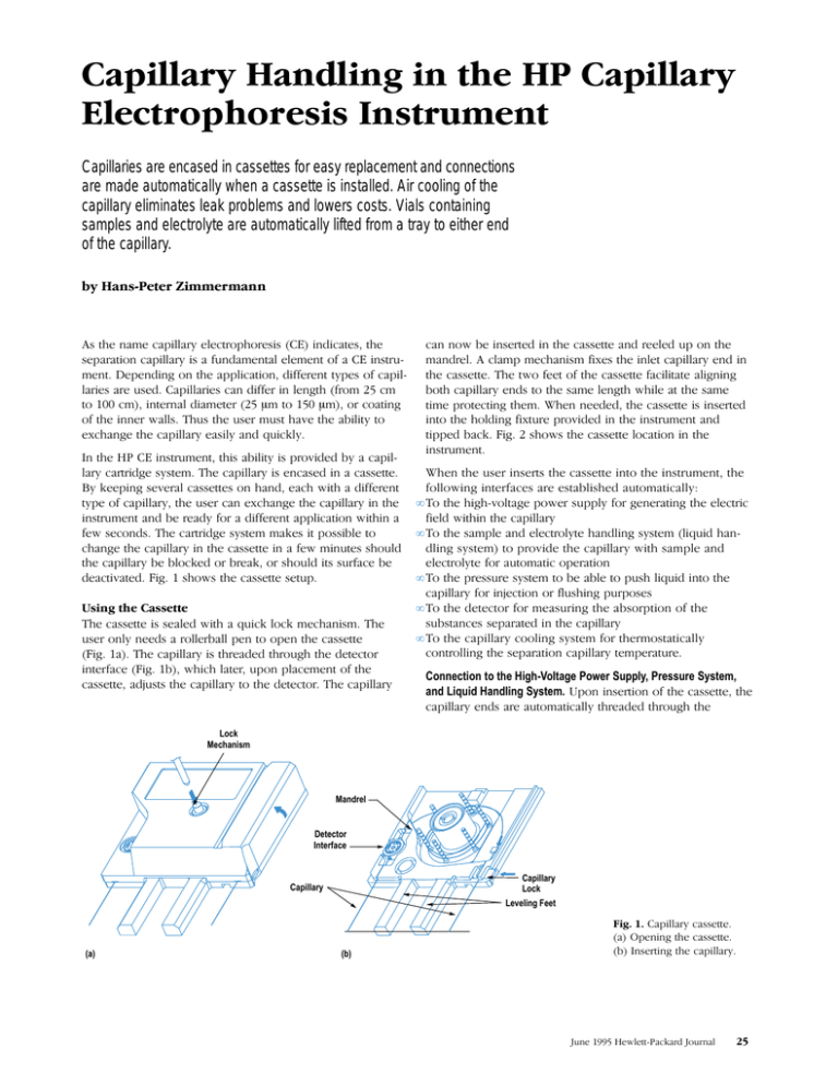
Capillaries are encased in cassettes for easy replacement and connections
are made automatically when a cassette is installed. Air cooling of the
capillary eliminates leak problems and lowers costs. Vials containing
samples and electrolyte are automatically lifted from a tray to either end
of the capillary.
, -! '& )"%%+2 %-+()!(+,", "'"-, -!
,)+-"(' )"%%+2 ", .'&'-% %&'- ( "',-+.3
&'- )'"' (' -! ))%"-"(' "+'- -2), ( )"%3
%+", + ., )"%%+", ' "+ "' %' -! +(& &
-( & "'-+'% "&-+ & -( & (+ (-"'
( -! "''+ 0%%, !., -! .,+ &.,- !/ -! "%"-2 -(
1!' -! )"%%+2 ,"%2 ' *."$%2
' -! "',-+.&'- -!", "%"-2 ", )+(/" 2 )"%3
%+2 +-+" ,2,-& ! )"%%+2 ", ', "' ,,--
2 $)"' ,/+% ,,--, (' !' ! 0"-! "+'-2) ( )"%%+2 -! .,+ ' 1!' -! )"%%+2 "' -!
"',-+.&'- ' +2 (+ "+'- ))%"-"(' 0"-!"' 0 ,(', ! +-+" ,2,-& &$, "- )(,,"% -(
!' -! )"%%+2 "' -! ,,-- "' 0 &"'.-, ,!(.%
-! )"%%+2 %($ (+ +$ (+ ,!(.% "-, ,.+ -"/- " ,!(0, -! ,,-- ,-.)
! ,,-- ", ,% 0"-! *."$ %($ &!'",& !
.,+ ('%2 ', +(%%+%% )' -( ()' -! ,,--
" ! )"%%+2 ", -!+ -!+(. ! -! --(+
"'-+ " 0!"! %-+ .)(' )%&'- ( -!
,,-- #.,-, -! )"%%+2 -( -! --(+ ! )"%%+2
' '(0 "',+- "' -! ,,-- ' +% .) (' -!
&'+% %&) &!'",& "1, -! "'%- )"%%+2 ' "'
-! ,,-- ! -0( - ( -! ,,-- "%"-- %" '"'
(-! )"%%+2 ', -( -! ,& %' -! 0!"% - -! ,&
-"& )+(--"' -!& !' ' -! ,,-- ", "',+-
"'-( -! !(%"' "1-.+ )+(/" "' -! "',-+.&'- '
-")) $ " ,!(0, -! ,,-- %(-"(' "' -!
"',-+.&'-
•
•
•
•
•
!' -! .,+ "',+-, -! ,,-- "'-( -! "',-+.&'- -!
(%%(0"' "'-+, + ,-%",! .-(&-"%%2
( -! !" !3/(%- )(0+ ,.))%2 (+ '+-"' -! %-+"
"% 0"-!"' -! )"%%+2
( -! ,&)% ' %-+(%2- !'%"' ,2,-& %"*." !'3
%"' ,2,-& -( )+(/" -! )"%%+2 0"-! ,&)% '
%-+(%2- (+ .-(&-" ()+-"('
( -! )+,,.+ ,2,-& -( % -( ).,! %"*." "'-( -!
)"%%+2 (+ "'#-"(' (+ %.,!"' ).+)(,,
( -! --(+ (+ &,.+"' -! ,(+)-"(' ( -!
,.,-', ,)+- "' -! )"%%+2
( -! )"%%+2 ((%"' ,2,-& (+ -!+&(,--"%%2
('-+(%%"' -! ,)+-"(' )"%%+2 -&)+-.+
Connection to the High-Voltage Power Supply, Pressure System,
and Liquid Handling System. )(' "',+-"(' ( -! ,,-- -!
)"%%+2 ', + .-(&-"%%2 -!+ -!+(. ! -!
Lock
Mechanism
Mandrel
Detector
Interface
Capillary
Lock
Leveling Feet
Capillary
(a)
(b)
)"%%+2 ,,--
)'"' -! ,,--
',+-"' -! )"%%+2
.' 0%--3$+ (.+'%
Air Ducts
Lid
Capillary
Cooling System
Cassette
Detector
Sample and
Electrolyte Tray
Electrodes
"!# # !( ""##
#& #!" # # "#!$# #!"
"#" # " # # )%# &! "$( #
!""$! "("# # $ "("#
"&" # "#$ #! $ #!"
# !( #!$ # " !$! " # $"
# #!$ # #$ #$ #! " #!
" # # # )%# &! "$( "
# #! # # # #& #!(# %" $!
("" # ( # #! ! "!# # # )
!( % !!" # #!" $" ( #
#! !!"% $!" # #! #$" !
#$ & " '#! "##( !
" ("" %" # # " ! # #!)
(# $! ! # $ # # #& #!" " ## #
!( # " #$ #$ # #
$
$" # !( ! # # " # " ""!( #
" # "!# !( "# # % " ## !""$!
" # % # # "#!$# "
" "!) " # !""" # ""##
& # #!" " !""" # " !$!
$ " # #! $" " ## # !( "
" "# # #! $! $" % " "
# # # # ## # #!
$ &##)! $!
Cassette
Capillary
Funnel
Silicon Rubber Seal
Electrode Housing
Platinum Electrode
#! #"
Insulation Plate
Cassette
Capillary
Slit
Lamp Housing
Capture Funnel
Spectrometer
Housing
Interface
Body
(a)
Detector interface. (a)
Sliding in the cassette. (b)
Final position.
(b)
housing so that the pressure inside the vials presses liquid
into the capillary.
the buffer, the quartz wall, and the polymer coating, and P is
the power level inside the capillary.
Connection to the Diode Array Detector. When the capillary is
threaded through the detector interface, it is aligned radially
by a VĆshaped slot to the slit in the detector interface, which
shades the capillary and leaves only the detection window
open. The correct axial position of the capillary relative to
the slit is achieved by a small stopper affixed to the capilĆ
lary. The size of the slit depends on the internal diameter of
the capillary, so different detector interfaces must be used
for the different capillary types. The correct choice of interĆ
face for each type of capillary is indicated by a color code.
Using typical substance values and measures, equation 1
predicts a temperature difference between the core and the
outside of the capillary of about 2.0 degrees with a power of
4.5W and a 1Ćm capillary length. The temperature gradient
within the capillary only plays a minor part. The main conĆ
tributor to the temperature rise in the core is the heat transĆ
fer to the ambient air at the capillary outer surface. This temĆ
perature difference can be calculated according to the
following equation:1
The detector interface floats in the cassette with a clearance
of ±1 mm. When the cassette is tipped back, the detector
interface is automatically adjusted to the detection slit by a
capture funnel (see Fig. 4).
Connection to the Capillary Cooling System. For cooling and
temperature control of the separation capillary, air is blown
into the capillary cassette at high speed. The capillary cooling
system is located in the upper back part of the instrument
(see Fig. 2). When the lid is closed, air ducts in the lid autoĆ
matically link the cooling system to the cassette. The function
of the capillary cooling system is described in more detail in
the next section.
Depending on the applied field strength and conductivity of
the buffer located in the capillary, there is an energy throughĆ
put of up to 6W in the capillary during analysis. If the capilĆ
lary were cooled only by natural convection, the liquid core
in the capillary would rise to more than 80°C above room
temperature in a 1Ćm capillary at maximum power. This might
cause destruction of sensitive samples or even boiling of the
buffer. Fig. 5 shows the setup and the different capillary and
fluid temperatures Tc, T1, T2, T3, and Tf.
The temperatures in the capillary can be calculated accordĆ
ing to Newton's Law: For the temperature difference in the
core, the following is true:1
1 r
1 r
1
DT T c T 3 P
ln 2 ln 3 ,
2pL 2k b k s r 1 k p r 2
(1)
where r1, r2, r3, and L are the dimensions of the capillary
(see Fig. 5), kb, ks, and kp are the thermal conductivities of
DT T 3 T f P ,
2pLr 3h
(2)
where h is the heat transfer coefficient at the capillary surĆ
face.
Unfortunately, the temperature drop at the capillary surface
is not as easily calculated as equation 2 suggests, since the
heat transfer coefficient h has a nonlinear dependence on
the flow velocity and the temperature of the surrounding
coolant. Fig. 6 shows the temperature rise in the core (Tc-Tf)
as a function of flow velocity for air and for a typical cooling
liquid (fluorocarbon FC77 from 3M) with a power dissipation
of 4.5 W/m in the capillary.
Fig. 6 shows that when cooling the capillary with forced air,
above a flow velocity of about 10 m/s, improvements in coolĆ
ing performance cannot be achieved. For liquid cooling, the
temperature rise inside the capillary is about 3.6 times lower
than for air cooling at equal velocity, according to equation 2.
Flow velocities as high as with air, however, can hardly be
Capillary
L
Fused Silica
r3,T3
r2,T2
Cooling
Fluid
r1,T1
Electrolyte
Tf
Polyimide
Coating
Tc
Temperatures and radii of fused silica capillaries.
June 1995 HewlettĆPackard Journal
In the past few years, methods offering the possibility of transforming 3D CAD
methods were pursued in the HP CE project, two ways to get a resin-plastic part
data directly into a ready-to-install part have experienced a steep upturn. These
and a third method to get an alumina part:
methods, which have been commercially available for about ten years now, are
• 3D data stereolithography process vacuum casting plastic model
generally known under the catchword “rapid prototyping.” Some of these methods • 3D data Solider process vacuum casting plastic model
and their combination with different replication techniques have reached the real
• 3D data STL file (Fig.1) stereolithography process STL model (Fig. 2) aim of rapid prototyping, namely the reduction of time to market. Within the HP
vacuum casting with silicone wax model (Fig. 3) ceramic shell for
capillary electrophoresis (CE) project, rapid prototyping methods became indistraditional investment casting for alumina parts (Fig.4).
pensable, not only because of the ambitious project schedule, but also because of
The real rapid prototyping step results in directly translating the 3D construction
the fact that some parts, because of their complexity, could not have been prodata into a solid part. The principle of all three methods mentioned above is simiduced in the traditional way without substantial compromises.
lar: a 3D computer model is split into layers of a certain thickness by software.
At the Waldbronn Analytical Division, these methods were used for the first time,
Various methods are applied to copy the section in question to materials such
involving significant risk because none of the people concerned could rely on peras photopolymers or powdery thermoplastics by using different reproduction
sonal experience. Another reason for using rapid prototyping methods certainly
techniques. This procedure is repeated until the whole part, composed of hunwas the cost aspect. However, it proved necessary to balance the requirements of
dreds of layers, is complete (see Fig. 5).
the individual development steps, the time available, and the complexity of the
individual parts against one another. In accordance with part requirements, three
Fig. 1. STL file created with a CAD application.
Fig. 2. STL model.
realized with liquids. At typical velocities of about 0.5 m/s
with liquid cooling, the difference from highĆspeed forcedĆair
cooling only is about 5°C (8.8° for air; 3.9° for liquid) with a
4.5 W/m energy throughput in the capillary. The advantage
of air cooling versus liquid cooling is that capillary handling
is significantly easier for the user. When exchanging the capĆ
illary, no liquid has to be drained and no costly sealing of the
cassette is needed. With air as the coolant, low leakage has
no disturbing influence. Also, no expensive cooling fluids
are necessary, which lowers the cost of ownership.
Temperature Rise Inside Capillary ( C)
70
60
50
40
Because of these advantages of air cooling, we decided that
an excess temperature of five degrees in the capillary core
could be accepted. In the HP CE instrument, forcedĆair capĆ
illary cooling is used with air velocities of about 10 m/s at
the capillary.
30
20
10
0
0
2
3
6
8
Velocity of Cooling Fluid (m/s)
Forced-Air Cooling
Liquid Cooling (FC77)
Temperature rise inside capillary.
June 1995 HewlettĆPackard Journal
10
12
Because the mobility of the substances in the capillary
changes by about 2% per degree, another important requireĆ
ment of the cooling system is the ability to adjust the temĆ
perature of the cooling air with a precision of ±0.1 degrees
to suppress variations in room temperature. This is achieved
by a Peltier heat exchanger element regulated by three temĆ
perature sensors. This element makes it possible to adjust
Depending on the method applied, the 3D data has to be prepared in different ways
(e.g., support framework). Regarding the actual formation of the part, however,
each method has its process-specific advantages and disadvantages.
In qualification of these rapid prototyping methods, however, it must be pointed out
that the parts cannot be used without costly subsequent treatment and replication—preferably with silicone—if specific requirements on surface quality, accuracy, and stability are to be met.
Martin Bäuerle
R&D Engineer
Waldbronn Analytical Division
Fig. 3 Wax model.
Part to Be Built
Current Layer
(Section)
Already Built Part
Fig. 5. The solid models are built up in layers.
Fig. 4. Production part.
." #, .'*,./, ,)' .( !,- &)1 '#(. .) °
#! -")1- ." -./* ) ." ))&#(! -3-.'
"- .) /.)'. ( ." #(-.,/'(. ."#- .-% #*, ),' 3 ." &#+/# "(&#(! -3-.' -")1( #( #! ,#& &)1, ,1- #, *-. ." ". 2"(!, ) ."
&.#, ')/& ( &)1- ." ))& ), 1,' #, .)1,." --.. .",)/!" ." #, /.- #( ." &# ,)' .", ."
#, #- % .) ." ". 2"(!, " &.#, &'(. #& .) &#0, /* .) ) ))&#(! *)1, ( /* .) ) ".#(! *)1, .) ." *#&&,3 ))&#(! #,/#. /- )
." ,&.#0&3 &)1 ##(3 ) &.#, &'(. .", #- *)1, #--#*.#)( ) /* .) . ." ". -#(% ) ." &.4
#, ')/& ) ,')0 ."#- ". ." ". -#(% #- ),4#,
))& 3 ( 2#& 0(.#&.), (.#&.), &.#, ". 24
"(!, ( ,#0, &.,)(#- , &). #( ." ))&#(!
-3-.' ' #( .1) #-)&.#(! )' -"&&-
'*&- ( &.,)&3.- , #( -'&& 0#&- ) '& ), '&
0)&/' #( #,/&, .,3 ,#(! " .,3 ,#(! ( *. '2#'/' ) 0#&- ". 2"(!, #( ." (., ) ."
.,3 ,#(! ( )((. .) ( 2.,(& ))&#(! ." ),
$/-.#(! ." 0#& .'*,./, " ". 2"(!, #- (
2'*& ) -0,& *,.- ) ." #(-.,/'(. .". 1,
-#!( /-#(! ,*# *,).).3*#(! - 2*&#( )0 "
.,3 ,#(! ,-.- )( .", ,)&&,- . #.- *,#'., ( #- ,#0(
3 -,0) ').), 0# */&&3
) "#0 "#!" -'*& .",)/!"*/. #( #(-.,/'(. ."
-/**&3 ) -'*&- ( &.,)&3.- .) ." .1) *#&&,3 (-
'*&- ( &.,)&3.- #( ." .,3 "0 .) *)-#.#)( .
)." ." *#&&,3 #(&. ( ." *#&&,3 )/.&. /- ."
.,3 ,#(! '/-. , .) ,).. ." 0#&- '/-. &# . ,)'
." .,3 .) ." *#&&,3 (- "#- .-% #- *, ),' 3 ."
&# . ')/&- 1) &# . ')/&- &# . ." 0#&- /* .) ." *#&&,3
(- ( ."#, &# . ')/& ')0- 0#&- .) (&
/( 1&..4%, )/,(&
Peltier Cooler
Foam Cover
Blower for Peltier Cooling
Blower for
Capillary Cooling
Foam Base
Heat Exchanger for
Capillary Cooling
Air Inlet to Cassette
Air Outlet to Cassette
'%"( * "!' !' '%"+' ! &( "
! )& ! % *' %& '%"+' %" &,
#!&% "'' & %' # & &'(# "%& &)% )!'& %&' ' #%")& %!,
" && '" " ' )& ! ' ('"& #% )
! #"&'"! '% ' ' #%+ !' ' ' #%+
"('' "% ' ' %#!& !' "( & !& '' '
(&% ! "* ( " ' '%+ #'+ '" (& "%
""! &+&' & # )& ! "* ( "% '%"+' )& "!
!! )& ' ' #%+ "('' "*& ' %!' %,
'"!& " & # '" "' &#%'+ % '& #,
#%" "*& (% %#!& !' ! #%+ #%"!,
'"!! '" #%" ! #%
" )" & # )#"%'"! ' )& % & *' #&
*"& '! %!& % #(! (#"! !'"! &!&') !& " ' &#%'"! #%+ *"( % ! '&
Capillary
Electrodes
48-Position Tray for Sample
and Electrolyte Vials
Prepunch Needle
Vial
Lift Finger
Buffer Replenishment
Belt for Tray Drive
Tray Motor
Tray Bearings
Lift Drive Mechanism
$( !! &+&' (! *'',% "(%!
Capillary
Injection System
V
+p
mbar
Flexible
Tube
Electrode
Lift Head
Vial
–p
Vial Cap
Prepunch
Needle
Connection to the injection system.
process, so a punching needle is located in the lift head to
prepunch the caps. In operation, the vial is held by a kind of
pliers and is pressed onto the punching needle by a spring
before being lifted to the capillary. A ringĆshaped blade seals
the prepunch needle to the vial cap. The lift presses the cone
of the prepunch needle against the seal at the electrode
housing (the seal can be seen in Fig. 3), thereby providing
the seal between the vial and the capillary. Pressure for
flushing or injection can then be applied to the vial through
a bore in the prepunch needle. The final position of the vial
is shown in Fig. 9.
I would like to acknowledge the contributions of John ChrisĆ
tianson, who set the directions for the capillary and liquid
handling techniques in the HP CE instrument. Also, special
thanks to Rolf Dörrmann and Greg Wilson for their support
during the project.
1. J.H. Knox and K.A. McCormack, ``Temperature Effects in Capillary
Electrophoresis, Part 1: Internal Capillary Temperature and Effects
upon Performance," , Vol. 38, no. 3/4, February
1994, pp. 207Ć221.
June 1995 HewlettĆPackard Journal
