JOURNAL HEWLETT' PACKARD
advertisement
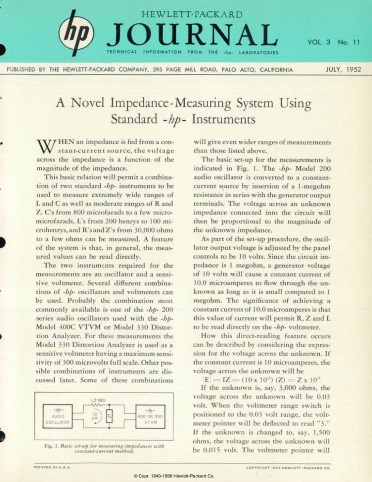
HEWLETT' PACKARD JOURNAL T E C H N I C A L I N F O R M A T I O N F R O M T H E - h p - VOL. 3 No. 11 L A B O R A T O R I E S PUBLISHED BY THE HEWLETT-PACKARD COMPANY, 395 PAGE MILL ROAD, PALO ALTO, CALIFORNIA JULY, 1952 A Novel Impedance -Measuring System Using Standard -hp- Instruments WHEN an impedance is fed from a con stant-current source, the voltage across the impedance is a function of the magnitude of the impedance. This basic relation will permit a combina tion of two standard -hp- instruments to be used to measure extremely wide ranges of L and C as well as moderate ranges of R and Z. C's from 800 microfarads to a few micromicrofarads, L's from 200 henrys to 100 microhenrys, and R'sandZ's from 30,000 ohms to a few ohms can be measured. A feature of the system is that, in general, the meas ured values can be read directly. The two instruments required for the measurements are an oscillator and a sensi tive voltmeter. Several different combina tions of -hp- oscillators and voltmeters can be used. Probably the combination most commonly available is one of the -hp- 200 series audio oscillators used with the -hpModel 400C VTVM or Model 330 Distor tion Analyzer. For these measurements the Model 330 Distortion Analyzer is used as a sensitive voltmeter having a maximum sensi tivity of 300 microvolts full scale. Other pos sible combinations of instruments are dis cussed later. Some of these combinations Fig. 1. Basic set-up for measuring impedances with constant-current method. P R I N T E D I N will give even wider ranges of measurements than those listed above. The basic set-up for the measurements is indicated in Fig. 1. The -hp- Model 200 audio oscillator is converted to a constantcurrent source by insertion of a 1 -megohm resistance in series with the generator output terminals. The voltage across an unknown impedance connected into the circuit will then be proportional to the magnitude of the unknown impedance. As part of the set-up procedure, the oscil lator output voltage is adjusted by the panel controls to be 10 volts. Since the circuit im pedance is 1 megohm, a generator voltage of 10 volts will cause a constant current of 10.0 microamperes to flow through the un known as long as it is small compared to 1 megohm. The significance of achieving a constant current of 10.0 microamperes is that this value of current will permit R, Z and L to be read directly on the -hp- voltmeter. How this direct-reading feature occurs can be described by considering the expres sion for the voltage across the unknown. If the constant current is 10 microamperes, the voltage across the unknown will be E| = = IZ=(10x 10'6) (Z) ==Zx 10'5 If the unknown is, say, 3,000 ohms, the voltage across the unknown will be 0.03 volt. When the voltmeter range switch is positioned to the 0.03 volt range, the volt meter pointer will be deflected to read "3." If the unknown is changed to, say, 1,500 ohms, the voltage across the unknown will be 0.015 volt. The voltmeter pointer will U . S . A . C O P Y R I G H T © Copr. 1949-1998 Hewlett-Packard Co. 1 9 5 2 H E W L E T T - P A C K A R D C O . Fig. 2. Basic set-up for measuring capacity with constant-voltage method. then be deflected to read "1.5." In other words, the significant fig ures of the voltage value are the same as the significant figures of the impedance value. The voltmeter thus becomes a direct-reading impedance meter. Using the -bp- Model 400C VTVM with one of the 200 series oscillators, full-scale resistance or impedance values of 100, 300, 1,000, 3,000, 10,000, and 30,000 ohms are obtained. Table I at the end of the article gives the full-scale values of the various positions of the volt meter range switch. L MEASUREMENTS So far no mention has been made of frequency, since the resistance or impedance measurements can be made at any frequency within the range of the equipment. However, the adjustable frequen cy of the oscillator can be used in such a way as to permit direct read ings both of L and C. Consider first the measurement of L. When an in ductance is connected into the cir cuit of Fig. 1, the voltage across the inductance will be |E =(I)(27rf) (L) Now the factor (27rf) in the above expression can be adjusted to be a power of 10 by suitable adjustment of frequency. For example, if / is adjusted to be 159.2 cps, (or in round numbers 160 cps), the factor (2-n-f) will be equal to 103; if / is adjusted to be 1600 cps, (27rf) will be 104, etc. When (2Tri) is made equal to 10m, the voltage across the inductance will be E j = (lOxlO-6) (L) (10â„¢) = (L) (10°) This is the same type of relation ob tained earlier in the measurement of resistance and impedance where E was equal to (Z) (10'5). In those measurements it was unnecessary to adjust frequency to obtain a directreading impedance-measuring sys tem. But in this case, if frequency is adjusted to be 160, 1600, or 16,000 cps, the significant figures in the voltage and in the value of L are the same. Therefore, direct measure ments can be made of L. To take an example, assume that an inductance of 0.3 henry is to be measured. The generator could be set to 160, 1600, or 16,000 cps, but it is convenient to set it to 160 cps. The voltage across the inductance will then be E = (10 xlO'6) (6.28x160) (0.3) or E =0.003 volt When the voltmeter range switch is set to the 0.003- volt full scale posi tion, the meter pointer will directly indicate the value of the inductance (0.3h). The range of values of L that can be measured using various frequen cies is shown in Table I. It should be noted that the two lowest frequen cies listed in the inductance portion of the table are not direct-reading. The current is thus proportional to the value of C. To make the system direct-read ing, it is necessary that the signifi cant figures in the value of I be the same as the significant figures in the value of C. This condition can be achieved either by making the fac tors (E) and (27rf) both equal to powers of 10 or by making the prod uct of (E) and (2-n-f) a power of 10. To accommodate the frequency range of most -hp- oscillators, it is convenient to make the product of (E) and (2^0 a power of 10. This condition is best met by choosing an (E) of 8 volts and an / of 20, 200, etc. To describe how the method op erates, assume that a C of 1 micro farad is to be measured at a fre quency of 20 cps. The current flow ing in the circuit of Fig. 2 will be I = (E)(27rf)(C) = (8)(125.7 xlO-6) = 1 milliampere One milliampere flowing through the 100-ohm precision resistor im presses a voltage of 100 millivolts across the voltmeter. The voltmeter thus reads "1," the value of C. If the C MEASUREMENTS The constant-current system can value of C were half as large, i.e., 0.5 not be used to make direct-reading microfarad, only half as large a cur measurements of C, because the volt rent would flow and the voltmeter age across C and the value of C are reading would be only half as large. Using the constant-voltage circuit, related inversely rather than direct C's from 3 microfarads to approxi ly. However, the constant-current mately 3 mmf can be measured. The system can be used to measure C by full-scale values of the voltmeter po use of a simple nomograph. This sitions in terms of C are given in arrangement is described later. Table II. To obtain a system for direct-read ing measurements of C, it is neces C O N S T A N T - C U R R E N T sary to use the inverse or dual of the C M E A S U R E M E N T S constant-current system; that is, to Where the constant-voltage meth use a constant-voltage system in od described above is suitable for which the current will be a function of C. A suitable arrangement is illus trated in Fig. 2. The oscillator is a low-impedance constant-voltage type such as the -bp- Models 200A, 200B, 200C, etc. The large series re sistance of the constant-current sys tem is replaced with a small preci sion resistance across which is con Fig. 3. Inherent error caused by voltmeter nected the voltmeter. The current loading and by reduced current. Plotted for case where unknown is a pure resis flowing in such a circuit is tance. Voltmeter impedance is assumed to I - E/X - (E) (2^-f) (C) be entirely resistive. © Copr. 1949-1998 Hewlett-Packard Co. measuring very small values of C, the constant current method is suit able for measuring very large values of C. The range of values that can be measured with the set-up of Fig. 1 is shown in Table II. Constant-current C measurements are made in the same general manner as constant-current measurements 'of R, Z, and L. However, the result ing voltmeter readings must be con verted by use of the nomograph (see back page). For convenience, C measurements are made at frequen cies of 20 cps, 200 cps, etc. To facili tate use of the nomograph, the con stant-current portion of Table II is arranged to indicate the maximum and minimum value of each switch setting at each frequency. CALIBRATION Fig. 4 shows the operating set-up for making measurements with either the constant-current or con stant-voltage methods. The constantcurrent set-up can be calibrated by plugging the -hp- Model 470D 100ohm precision shunt into the volt meter terminals and adjusting the oscillator voltage until the voltmeter indicates exactly 1 millivolt. The de sired current of 10 microamperes will then be obtained. For constant-voltage measure ments, the 470D can be used as the 100-ohm precision resistor across which the voltmeter is connected. To calibrate the set-up, adjust the oscillator voltage to be 8 volts when the shunt is removed and the capac ity shorted. ERRORS In general, the error inherent in the constant-current system of meas urement increases with the magni tude of the impedance being meas ured. Greatest error occurs in the measurement of resistance. Where the impedance being measured is substantially reactive, i.e., in meas urements of C, L, and Z, the error is considerably less than that obtained in measurements of R. There are two principle factors that contribute to the inherent error in constant-current type measure ments. These are (a) the relation of the impedance of the unknown to the 1 -megohm impedance of the cur rent source; and (b) the loading effect on the unknown by the volt meter impedance. Fig. 4. Generalized set-up for constantAn indication of error is given in current or constant-voltage measurements, 47 OD 100-ohm shunt is conveniently Fig. 3. The errors shown have been -hparranged to be plugged directly into volt calculated for the case where the un meter terminals. known is a pure resistance, the worst case, and for several voltmeter im the range of the measurements can pedances. In calculating these values, be extended upward. Or, second, the the voltmeter •was assumed to have a constant current can be increased pure resistive input. Actually, VT- from 10 to 31.6 microamperes so that VM's have associated with them a the minimum value of measurable capacitive component which makes impedances can be extended down their input impedance a function of ward. With a constant current of frequency. Therefore, greater accu 31.6 microamperes, it is convenient racy will, in general, be obtained in to make readings on the "wrong" constant-current type measurements scale of the meter face. The "wrong" at the lower frequencies. scale is used in this case because the Measurements of C with the di voltage across the unknown will be rect-reading constant-voltage system 3.16 (10 db) times as great as with can be made with excellent accuracy. a current of 10 microamperes and In general, the inherent error will because the meter scales of -hp- volt not exceed a few tenths of a per cent. meters are separated by 10 db. This small error will be swamped by The widest range of measurements practical errors such as errors in fre will be obtained by using the -hpquency setting, in voltmeter read Models 205A or 205AG Audio Sig ings, etc. nal Generators. The Model 205 pro vides a maximum output voltage of GENERAL Full scale-values of R, Z, and L are 150 volts. With such a large gener given in Table I for the various posi ator voltage the source impedance tions of the voltmeter switch. can be made very large and at the The table is designed for use with same time a large constant current a constant current of 10 microam can be obtained so that small impe peres. If a series resistance of 1 meg dances can be measured. ohm is used, nearly any of the -hpTwo of the -hp- voltmeters are audio oscillators can be used to pro especially suited for measuring the vide the 10 volts necessary to obtain voltage across the unknown. The 10 microamperes. -hp- Model 400C has a full-scale A number of -hp- oscillators will sensitivity of 1 millivolt and can be provide considerably more than 10 used with a current of 10 microam volts. The Models 200A and 200B peres to make measurements as low provide approximately 25 volts, as 100 ohms full scale. The -hpwhile the Model 201B will provide Model 330 distortion analyzers, more than 40 volts. Where one of which are capable of being operated these instruments is available, the as high-sensitivity voltmeters, pro additional voltage can be used in vide a full-scale sensitivity of 300 either of two ways to increase the microvolts. The 330 can be used to range of measurements. First, the make measurements as low as 30 series resistance can be made several ohms full scale. However, the input times larger than 1 megohm so that impedance of the 330 is 0.2 meg© Copr. 1949-1998 Hewlett-Packard Co. ohm in parallel with approximately 40 mmf so that the 330 is less suit able than the Model 400C for meas urements of large impedances. A little experimenting with the particular combination of instru ments at hand will indicate the most convenient method of making meas urements. TABLE I ACKNOWLEDGMENT The foregoing arrangement for measuring impedances with the con stant-current system was suggested by Mr. Mario Novajra of Poirino, Italy. A resume of the above system printed on durable paper will be supplied free upon request while supply lasts. TABLE II C MEASUREMENTS NOMOGRAPH FOR "1" RANGES OF VOLTMETER .6 1.0 METER SCALE CAPACITY 2 5 2 0 1 5 1 2 1 0 9 NOMOGRAPH FOR "3" RANGES OF VOLTMETER . 4 . 6 . 8 1.0 METER SCALE CAPACITY 2.5 © Copr. 1949-1998 Hewlett-Packard Co.


