Document 12961155
advertisement
! Mixed-signal testers are frequently used as specialized automatic test
equipment in various test applications. The real-time digital signal
processors in the HP 9493 mixed-signal LSI test system can perform
complex tests for next-generation telecommunication devices.
! . 4(% .%84 '%.%2!4)/. /& 7)2%,%33 #/--5.)#!4)/.3 3934%-3
()'(>15!,)49 4%,%#/--5.)#!4)/. !.$ #/-0!#4 %15)0-%.4 7),,
"% !#()%6%$ "9 53).' .%7 ()'(,9 ).4%'2!4%$ -5,4)&5.#4)/.!,
-)8%$ $)')4!, !.$ !.!,/' $%6)#%3 )8%$>3)'.!, 4%34%23 ,)+%
4(% #!. 4%34 4(%3% $%6)#%3 !.9 /& 4(% .%7%2 4%,%>
#/--5.)#!4)/. 3934%-3 53% #/-0,)#!4%$ -/$5,!4)/. -%4(>
/$3 35#( !3 $)&&%2%.4)!, 15!$2!452% 0(!3% 3()&4
+%9).' 7()#( #2%!4%3 30%#)!,):%$ 7!6%&/2-3 4(!4 !2% 6%29
$)&&)#5,4 4/ !.!,9:% )4( )43 "5),4>). $)')4!, 3)'.!, 02/#%33/23
3 4(% #!. !,3/ "% 53%$ 4/ 3/,6% 3/-% /& 4(%3%
$)&&)#5,4 3)'.!, !.!,93)3 02/",%-3
. '%.%2!, ! -)8%$>3)'.!, 4%34%2 )3 ./4 !. ).3425-%.4 &/2
-%!352%-%.4 "54 3%26%3 !3 !54/-!4)# 4%34 %15)0-%.4 ). 4(%
02/$5#4)/. !2%! (% -/34 )-0/24!.4 2%15)2%-%.4 )3 (/7
15)#+,9 &!),).' $%6)#%3 #!. "% 2%*%#4%$ &2/- ! ,!2'% .5-"%2
/& 0!33).' $%6)#%3 //$ 2%0%!4!"),)49 7()#( )3 ! &5.#4)/. /&
3934%- 34!"),)49 !.$ 53!"),)49 !2% !,3/ 2%15)2%$ &/2 ()'(
02/$5#4)6)49
!.9 /& 4(% 4%343 0%2&/2-%$ "9 -)8%$>3)'.!, 4%34%23 $/ ./4
(!6% 02%#)3% 30%#)&)#!4)/.3 "%#!53% /& 4(% #/-0,%8)49 /& 4(%
$%6)#% 5.$%2 4%34 .3)$% ! -)8%$>3)'.!, $%6)#% !2% -!.9 $)')>
4!, !.$ !.!,/' 3)'.!,3 !.$ $)')4!, 3)'.!,3 -!9 #/22504 !.!,/'
3)'.!,3 !.$ 6)#% 6%23! 3 ! 2%35,4 3/-% 4%343 (!6% 4/ "%
'5!2!.4%%$ 34!4)34)#!,,9 /2 %80%2)-%.4!,,9 (% -%!352%-%.4
/& 4(% 6%#4/2 %22/2 /.% /& 4(% -/34 )-0/24!.4 4%34 0!2!-%4%23
&/2 $%6)#%3 "%,/.'3 4/ 4()3 #!4%'/29 3/ )4 )3 ./4
!. 5.&!-),)!2 490% /& 4%34 &/2 ! -)8%$>3)'.!, 4%34 3934%,)+% 4(% Data
Input
X
Serial-toParallel
Converter Y
Differential
Encoder
#4/"%2 %7,%44>!#+!2$ /52.!,
I-Channel
Waveform
Roll-Off
Filter
Q-Channel
Waveform
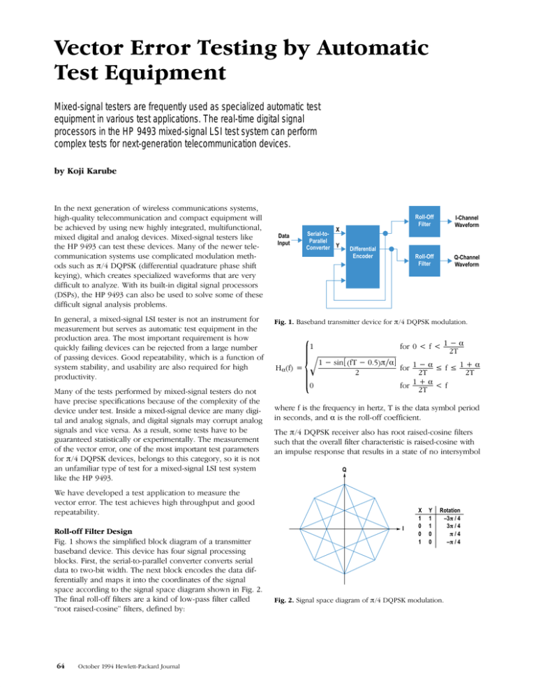
!3%"!.$ 42!.3-)44%2 $%6)#% &/2 -/$5,!4)/.
& =
&/2< & &/2< &
3).< &
< &/2< & 7(%2% & )3 4(% &2%15%.#9 ). (%24: )3 4(% $!4! 39-"/, 0%2)/$
). 3%#/.$3 !.$ )3 4(% 2/,,>/&& #/%&&)#)%.4
(% 2%#%)6%2 !,3/ (!3 2//4 2!)3%$>#/3).% &),4%23
35#( 4(!4 4(% /6%2!,, &),4%2 #(!2!#4%2)34)# )3 2!)3%$>#/3).% 7)4(
!. )-05,3% 2%30/.3% 4(!4 2%35,43 ). ! 34!4% /& ./ ).4%239-"/,
Q
% (!6% $%6%,/0%$ ! 4%34 !00,)#!4)/. 4/ -%!352% 4(%
6%#4/2 %22/2 (% 4%34 !#()%6%3 ()'( 4(2/5'(054 !.$ '//$
2%0%!4!"),)49
" )' 3(/73 4(% 3)-0,)&)%$ ",/#+ $)!'2!- /& ! 42!.3-)44%2
"!3%"!.$ $%6)#% ()3 $%6)#% (!3 &/52 3)'.!, 02/#%33).'
",/#+3 )234 4(% 3%2)!,>4/>0!2!,,%, #/.6%24%2 #/.6%243 3%2)!,
$!4! 4/ 47/>")4 7)$4( (% .%84 ",/#+ %.#/$%3 4(% $!4! $)&>
&%2%.4)!,,9 !.$ -!03 )4 ).4/ 4(% #//2$).!4%3 /& 4(% 3)'.!,
30!#% !##/2$).' 4/ 4(% 3)'.!, 30!#% $)!'2!- 3(/7. ). )' (% &).!, 2/,,>/&& &),4%23 !2% ! +).$ /& ,/7>0!33 &),4%2 #!,,%$
;2//4 2!)3%$>#/3).% &),4%23 $%&).%$ "9
Roll-Off
Filter
I
X
1
0
0
1
Y
1
1
0
0
Rotation
–3 / 4
3 / 4
/4
– / 4
)'.!, 30!#% $)!'2!- /& -/$5,!4)/.
Q
Q
I-Channel
Waveform
Roll-Off
Filter
I2
Re
Fourier
Transform lm
I
I
Q-Channel
Waveform
Roll-Off
Filter
tan–1
Extracted
Symbol
Timing
Q2
Conventional method of symbol timing extraction.
(b)
(a) IĆQ signal without filters. (b) IĆQ signal with root raisedĆ
cosine filters.
interference, as shown Fig. 3b. For this test the receiver filĆ
ters are emulated in the HP 9493 test system using the digital
signal processing capabilities. To obtain the required impulse
response, we use 8ĆsymbolĆdeep FIR (finite impulse response)
filters, where 8ĆsymbolĆdeep means that the duration of the
filter impulse response corresponds to eight data symbol
times. The design employs virtual oversampling1 and multiĆ
rate techniques1 to achieve highĆresolution delay adjustment
and high throughput.2
The Research and Development Center for Radio Systems in
Japan specifies the vector error as follows.3 The ideal transĆ
mitted signal after final filtering is:
S(k) = S(k - 1)ej(/4+B(k)/2)
where B(k) is defined by the following table.
0
0
1
1
0
1
1
0
0
1
2
3
The actual transmitted signal after final filtering is:
Z(k) = [C0 + C1{S(k) + E(k)}]Wk
where W = edr+jda for phase offset da (radians/symbol) and
amplitude change dr (nepers/symbol)
C0 = arbitrary complex constant representing the
offset of the origin caused by imbalance of the
quadrature modulator
C1 = arbitrary complex constant determined by the
phase and power of the transmitter
E(k) = vector error.
Then the sum of the squared vector errors is:
max
ȍ
2
|E(k)| +
k+min
max
ȍ ŤNJƪZ(k)W*k * C0ƫńC1Nj * S(k)Ť .
2
k+min
method of extracting the phase of the signal (symbol timing)
has to be designed. In concrete terms, the function of symĆ
bol timing extraction is to find the eight convergence points
of the filtered IĆQ signal shown in Fig. 3b.
The conventional method of extracting symbol timing is enĆ
velope detection of the squared signal as shown in Fig. 4.
The phase extracted by this method is a little different from
the best phase" because this method observes only a narĆ
row bandwidth around oneĆhalf the symbol frequency and
ignores the group delay of the actual devices. Fig. 5 shows
the timing error for this method of symbol extraction as a
function of the calculated vector error, obtained by simulaĆ
tion. According to this figure, timing error must be within 10
ns to achieve repeatability within less than 0.1%. Therefore,
instead of the envelope detection method, we adopted a
specialized search method that finds the actual minimum
vector error.
In a /4 DQPSK receiver, the extracted symbol timing is fed
back to the digitizer clock inputs. In the HP 9493, this is
simulated by using adjustableĆdelay filters in front of the
signal processing.
Fig. 6 shows the simplified block diagram of the vector error
test. The test uses two 16Ćbit digitizers to digitize the I and Q
signals independently and uses two sets of realĆtime DSPs to
process both signals at the same time. Each digitized signal
with 16Ćbit resolution is transferred into the rollĆoff filters and
processed by one of the 8ĆsymbolĆdeep FIR filters. In effect,
there are 512 of these filters, each having a slightly different
delay. The delay is selected by feedback from subsequent
blocks. Next, gain error and offset are adjusted and then
1.0
Vector Error (%)
(a)
0.5
System designers attempt to minimize this error by selection
of C0, C1, and W.
To calculate the vector error, C0, C1, and W must be deterĆ
mined. For a baseband transmitter device, the frequency
offset described by W is zero because the I and Q signals
are observed without quadrature modulation that shifts the
signal frequency. The offset of the origin described by C0
can be obtained easily by statistics. To determine C1, a
0
–60
–30
0
30
60
Symbol Timing Error (ns)
Symbol timing error as a function of calculated vector error.
October 1994 HewlettĆPackard Journal
Real-Time Digital Signal Processor
Slicer
I-Channel
Waveform
16-Bit
1-MHz
Digitizer
Roll-Off
Filters
Statistics
and
Control
I2
err
Vector Error to
Test Program
Gain and Offset
Symbol Timing
L-Path
Real-Time Digital Signal Processor
Gain and Offset
Q-Channel
Waveform
16-Bit
1-MHz
Digitizer
Roll-Off
Filters
Q2
err
Statistics
and
Control
Slicer
Symbol Timing
,/#+ $)!'2!- /& 4(% 6%#4/2 %22/2 4%34
315!2%$ 6%#4/2 %22/23 !2% #!,#5,!4%$ "9 #/-0!2).' 4(%
!#45!, 39-"/, ,/#!4)/.3 ). 4(% < 0,!.% 7)4( 4(% )$%!, ,/#!<
4)/.3 7()#( !2% $%4%2-).%$ "9 4(% 3,)#%23 (% 34!4)34)#3 !.$
#/.42/, ",/#+ 3%!2#(%3 &/2 4(% "%34 39-"/, 4)-).' 4/ -).)<
-):% 4(% 6%#4/2 %22/2 "9 #(!.').' 4(% 2/,,</&& &),4%2 $%,!9
7()#( #(!.'%3 4(% 39-"/, 4)-).'
(% 2/,,</&& &),4%23 !2% $%3)'.%$ 4/ (!6% ! ()'( 6)245!, #/.6%2<
3)/. &2%15%.#9 /& 4)-%3 4(% 39-"/, &2%15%.#9 7()#(
#/22%30/.$3 4/ !"/54 <.3 $%,!9 2%3/,54)/. ). 4(% 2/50 $%,!9 ). 4(% "!.$ &2/- :%2/ 4/ 4(% "!5$ 2!4% #!53%3
39.#(2/.):!4)/. %22/2 .!,/' 4)-).' 3+%7 "%47%%. $)')4):%23
!,3/ $)2%#4,9 2%$5#%3 4(% !##52!#9 /& 4(% 6%#4/2 %22/2 -%!<
352%-%.4 . 4(% 4%34 3934%- 4(% %&&%#4 /& 4)-).'
3+%7 )3 %,)-).!4%$ "9 2%'5,!2 #!,)"2!4)/. 3/ 4(% 53%2 .%%$
#4/"%2 %7,%44<!#+!2$ /52.!,
/.,9 -!+% 352% 4(!4 4(% #!",% ,%.'4(3 /& 4(% #(!..%, !.$
4(% #(!..%, !2% 3!-% /. 4(% "/!2$
(% !54(/2 7/5,$ ,)+% 4/ 4(!.+ !-/25 !."! &/2 ()3
"%.#(-!2+ 4%34 (% !54(/2 7/5,$ !,3/ ,)+% 4/ 4(!.+ !,,
-%-"%23 /& 4(% !00,)#!4)/. %.').%%2).' '2/50 !4 !#()/*)
%-)#/.$5#4/2 %34 )6)3)/. &/2 4(%)2 '2%!4 #//0%2!4)/.
2/#()%2% !.$ !").%2 2%.4)#% !,, !25"% %4 !, ;$6!.#%$ )8%$<)'.!, %34).' "9 /#!,):%$
%34%2 00 <
< %3%!2#(
!.$ %6%,/0-%.4 %.4%2 &/2 !$)/ 934%-3
