The CLARREO Climate Benchmarking Mission:
advertisement
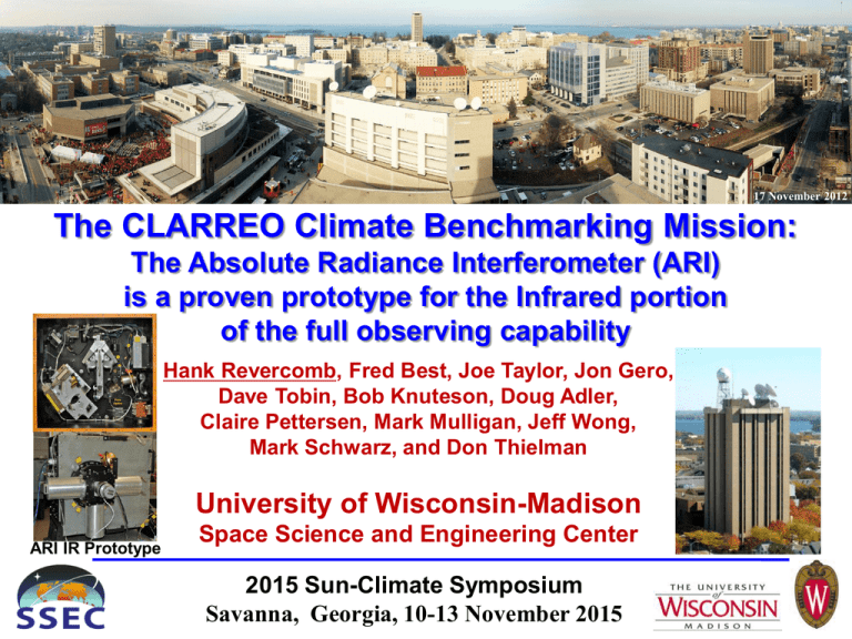
17 November 2012 14 February 2009 The CLARREO Climate Benchmarking Mission: The Absolute Radiance Interferometer (ARI) is a proven prototype for the Infrared portion of the full observing capability Hank Revercomb, Fred Best, Joe Taylor, Jon Gero, Dave Tobin, Bob Knuteson, Doug Adler, Claire Pettersen, Mark Mulligan, Jeff Wong, Mark Schwarz, and Don Thielman University of Wisconsin-Madison ARI IR Prototype Space Science and Engineering Center 2015 Sun-Climate Symposium Savanna, Georgia, 10-13 November 2015 Introduction to CLARREO • CLARREO (Climate Absolute Radiance & Refractivity Observatory) a 2007 Decadal Survey Tier 1 mission – IR & Reflected Solar spectra coupled with GPS RO offer (1) unprecedented measurement accuracy, 0.1 K IR brightness T, 0.4 % RS radiance, and 0.1 % GPS RO refractivity 5-20 km (all 3-sigma, proven on orbit with SI standards), (2) unbiased spatial and temporal sampling, and (3) much higher climate change sensitivity than existing climate records (from total integrated IR & Solar data) – Metrology lab on-orbit serves as “NIST in orbit” • CLARREO to Benchmark Earth’s climate – Analogous to marking a glacier’s current extent • CLARREO as an Inter-calibration Standard – GSICS (Global Space-based Inter-Cal System) – e.g. Greatly enhancing the value of the climate record from high spectral resolution IR sounders starting in 2002 (AIRS, IASI, CrIS) and RS sensors Cover of 2007 Decadal Survey 2 NASA CLARREO Timelines (Climate Absolute Radiance and Refractivity observatory) • 2008-2010 CLARREO –following the DS, NASA assigned mission responsibility to Langley Research Center (LaRC) – A Science Team was formed and detailed mission definitions debated (Pre-Phase A activities) – Mission Confirmation Review (MCR) passed successfully in November 2010 – IR and Reflected Solar instrument development conducted under NASA Instrument Incubator Program (IIP) and calibration system studies • 2011 CLARREO –funding profile removed from the president’s budget on 14 February • 2011-15 CLARREO – Science Team Pre-Phase A studies continue, resulting in Wielicki et al., BAMS publication and cover in Oct 2013 • 2012-2014 New Instrument Technologies -Achieved TRL 6 under NASA Instrument Incubator Program (IIP) / ESTO support of LASP for RS and UW-SSEC & Harvard for the IR Wielicki et al. 3 US President’s FY2016 Budget Request Includes a Pathfinder mission to kickoff CLARREO! (Climate Absolute Radiance and Refractivity Observatory) • “The CLARREO Pathfinder mission will demonstrate essential measurement technologies; validate the high accuracy radiometry required for long-term climate studies in support of other Decadal Survey and land imaging missions; and initiate measurements that will benchmark the shortwave reflectance and infrared climate record.“ • “NASA plans to host the two CLARREO Pathfinder instruments, Reflected Solar (RS) and Infrared (IR) spectrometers, on the International Space Station in FY 2019.” (budget $77 M) Slide 4 NASA PPBE Milestone Accomplished (Planning, Programming, Budgeting, and Execution) • Approach and Grass Roots Cost Estimates for the IR from U of Wisconsin-SSEC and RS inputs from U of Colorado LASP (who conducted NASA IIP developments) were provided in support of a credible plan to perform the Pathfinder ISS mission under assumed constraints and budget • The NASA PPBE Milestone qualifies the LaRC CLARREO project to implement the Pathfinder, if it is part of the final FY2016 appropriations Slide 5 NASA PPBE Process Diagram Slide 6 Topics 1) History (IR & Wisconsin slant) 2) ISS Pathfinder for CLARREO 3) Absolute Radiance Interferometer (ARI) CLARREO IR Prototype update International Space Station International Space Station A A ARI Section A-A ARI Lab Prototype ARI ISS RAM Space Earth 7 Earth Radiation Budget, the old way* 13 Oct 1959-Feb 1960 Explorer 7 The 1st meteorological satellite NASA just in its 2nd year instrument to observe the Earth Radiometer designed by Verner Suomi & Robert Parent Omni-directional spheres 3-color (black, white, gold) Spectrally integrated obs continue today today An outgrowth of measuring the energy budget of a corn field Spheres also on TIROS 3, 4, 7 1961-63 * The right way then! 8 1966-1972 Black and White Flat Plate Radiometers followed for flux measurements of the Earth Radiation Balance Many flights carried Suomi/Parent Radiometers ESSA 3, 5, 7, 9 spinners, 1966-69 ITOS 1, 1970 NOAA 1, 1970 9 Active Cavity Radiometer, 1975-8 • Developed for UW ERBOS* mission • Electrical Substitution Cavity Radiometer chosen to improve flux accuracy • Designed with fast time constant response (15 ms) for scanning the Earth from a spinner • This UW program was cancelled, but the approach of measuring the total integrated Solar Reflected and Earth Emitted fluxes for studying Earth’s Climate continues today - Current US Earth Radiation Budget measurements from CERES followed those from ERB and ERBE. - New NASA Radiation Budget Instrument (RBI) is planned * Earth Radiation Budget Observing System, not selected 10 Fourier Transform Spectro-radiometer • 1978-1985: Designed high spectral resolution instrument for “Sounding” [T(p), WV(p)] from GEO leading to High-resolution Interferometer Sounder (HIS) aircraft sensor • Flew on high altitude NASA U2/ER2 aircraft 1985-1998 • 3-17 µm at 0.34 cm-1 resolution (Resolving power > 1700) • First demonstration of high vertical resolution sounding (2.53 times improvement) from high spectral resolution IR • Significant contribution to improved spectroscopy from accurately calibrated, long path atmospheric spectra We learned the virtues of high spectral resolution for improving absolute accuracy —uncertainties reduced from degrees to tenths of degrees! 11 Scanning HIS Aircraft Instrument (Scanning High-resolution Interferometer Sounder, HIS; 1998-present) Uplooking and Downlooking Spectra for Remote Sensing Michelson Interferometer Satellite Sensor Validation Proteus AIRS 12 1993-CLIMSAT: Jim Hansen, NASA GISS • Spectrally resolved IR and solar proposed to measure forcings & feedbacks - 3 instruments: – MINT: 6-40 µm Michelson Interferometer – EOSP: 0.4-2.25 µm Earth Observing Scanning Polarimeter – SAGE III: 0.29-1.02 µm Stratospheric Aerosol and Gas Experiment • Two Spacecraft for adequate sampling • Emphasized precision/self calibration • But expected to rely on observations from subsequent S/C having temporal overlap to achieve 2-decade observing goal 13 1996-Arrhenius: Jim Anderson, Harvard • Proposed observing system based on IR Spectrally resolved Radiances (6-44 µm) with 0.1 K 3-sigma accuracy, demonstrated on-orbit • Sampling studies showed importance of multiple, carefully chosen orbits • Evolved to add reflected solar and GPS Radio Occultation for Decadal Survey White Paper in 2005 (Harvard teamed with UW-SSEC, NIST, U of Colorado, SwRI, U of Graz) Slide 14 What would a Climate Program “Board of Inquiry” place at the top of the priority list? • We have a fundamental responsibility to future generations to put in place a climate record that is accurate in perpetuity, testable by scientists from any nation at any time in the future, and is global in coverage. • Long-term climate forecasts that are tested, trusted and systematically improved. • Eloquently supporting the argument that on-orbit accuracy verification & testing is a crucial requirement 15 2006 ASIC3 16 16 CM2 25-yr Annual Mean Trends Yi Huang thesis (Ramaswamy, advisor), 2008 Black dots indicate changes > 3 x standard deviation of unforced means Note OLR Insensitivity to the trends in Ts, Atmospheric T, WV, and Clouds 17 High Spectral Resolution Infrared Sounding from Polar Orbit 2006for operational weather AIRS 2002- 2011- CrIS (2211 ch) 1330 Suomi-NPP (NOAA/NASA) IASI (8461 ch) 0930 EUMETSAT METOP (2378 ch) 1330 NASA Aqua 1990/91 ITS (~CrIS) UW-SSEC led Design 1986- 1978- HIS, S-HIS, NAST-I Stepping stones HIRS (20 ch) 18 Topics 1) History (IR & Wisconsin slant) 2) ISS Pathfinder for CLARREO 3) Absolute Radiance Interferometer (ARI) CLARREO IR Prototype update International Space Station International Space Station A A ARI Section A-A ARI Lab Prototype ARI ISS RAM Space Earth 19 Value of an ISS Pathfinder Mission An IR Prototype on ISS will provide, not only a tech demo for CLARREO cost and technical risk reduction, but also the start of an accurate climate benchmark, identified as critically important in the 2007 Decadal Survey. The key components supporting the above are • Measurement Accuracy: ARI has demonstrated the ability to fully meet the CLARREO 0.1 K 3-sigma requirement over the required spectral range, including the Far IR out to 50 microns. • Sampling Requirements: Needs for an initial benchmark (unbiased temporal and spatial sampling) are met by ISS below 52 degrees latitude. • Intercalibration: Use of the AIRS (on EOS Aqua) and CrIS (on Suomi NPP) at 0130/1330 local times, IASI (on EUMETSAT MetOp A and B) at 0930/2130 local times, and likely the Chinese sounder on (FY3E) at 0530/1730, provide good sampling to extend the benchmark to high latitudes for all but the Far IR portion of the spectrum. • Lifetime: No fundamental life limiting components are required for the sensor, and with ISS life extended until 2024 there is a good chance of creating the 5 year record needed for a credible benchmark. Slide 20 Current Sounders Show Significant Differences Mean Simultaneous Nadir Overpass (SNO) differences for 910-930 cm-1 0.5 BT Diff (K) 0.4 AIRS - IASI-A AIRS - IASI-B CrIS - IASI-A CrIS - IASI-B 0.3 >0.3 K 0.2 relative differences 0.1 0 -0.1 290 280 270 260 250 240 230 220 210 BT (K) 0.050 K Agreement SNOs: AIRS-IASIA, AIRS-IASIB, CrIS-IASIA CrIS-IASIB 200 Error-bars represent 190 statistical matchup uncertainty, not sensors uncertainty ARI would establish an absolute reference to better than 0.1K! 21 Current Approach to absolute assessment: SNPP Calibration Validation Campaign 2015 • Seven ER-2 science flights were conducted during the March 2015 airborne calibration validation campaign. Flights were based out of Keflavik Iceland with flights over the Greenland ice sheet. • The Scanning-HIS has a clear calibration traceability to NIST and many valuable satellite underflight datasets were collected. Google Earth Joe Taylor et al., talk 12.06 22 22 PRELIMINARY LW window differences 0.6 K 23 ARI Accuracy Offers Substantially Reduced Time to Detect Global Climate Change Achieving Climate Change Absolute Accuracy in Orbit, Example with factor of 2 shorter Time to Detect Trend Uncertainty (K/decade, 95% Confidence) Global Near Surface Air Temperature Wielicki et al., BAMS, 2013 Time to Detect (Years) 24 Topics 1) History (IR & Wisconsin slant) 2) ISS Pathfinder for CLARREO 3) Absolute Radiance Interferometer (ARI) CLARREO IR Prototype update International Space Station International Space Station A A ARI Section A-A ARI Lab Prototype ARI ISS RAM Space Earth 25 Key Instrument Performance Specifications On-Orbit Verification and Test System (OVTS) 2-4 sec CLARREO IR Pathfinder 26 Spectral Requirements Spectral Coverage & Resolution: 3-50 m or 200-3000 cm-1 with =0.5 cm-1 (includes Far IR to capture most of the information content and emitted energy, & instrument independent scale) IASI IASI L1C 1cm MaxOPD AIRS CrIS CrIS AIRS High Accuracy IR Radiances-CLARREO wavenumber 27 CLARREO IR Accuracy 0.12 0.06 0.04 0.02 CLARREO 3-sigma Requirement CLARREO Requirement 0.10 Brightness T Error [K] Brightness T Error [K] Radiance Accuracy: <0.1 K 2-sigma brightness T for 0.12 combined measurement and sampling uncertainty (each <0.1 K 3-sigma) for annual averages of large 0.10 regions (to approach goal of resolving a climate change signal in the decadal time frame) 0.08 0.08 0.06 0.04 0.02 0.00 2000.00 220 200 220 dT=45 mK, de=0.0006, dTtel =20 mK, Tbb=300K, 240 260 280Tstr=285 K 240 260 280 Scene Temperature [K]300 300 320 Scene Temperature [K] 200 cm-1 200 cm-1 500 cm-1 500 cm-1 1000 cm-1 1500 1000 cm-1 Slide 28 1500 2000 cm-1 2000 cm-1 320 Absolute Radiance Interferometer (ARI): Definitions of key components of prototype instrument • Calibrated Fourier Transform Spectrometer (CFTS): – FTS with strong flight heritage from ABB/Bomem, Inc. – 3 Spectral bands covering 3-50 µm – 2 Cavity Blackbody References for Calibration (1 + Space On-orbit) • On-orbit Verification and Test System (OVTS): – On-orbit Absolute Radiance Standard (OARS) cavity blackbody using three miniature phase change cells to establish an accurate temperature scale from 40, to +30 C – On-orbit Cavity Emissivity Module (OCEM)-Heated Halo using a blackened, Heated Halo source that allows the FTS to measure the broadband spectral emissivity of the OARS to better than 0.001 – OCEM-QCL* using a quantum cascade laser source to monitor changes in the mono-chromatic cavity emissivity of the OARS – On-orbit Spectral Response Module* (OSRM) using the same QCL to measure the FTS instrument line shape *Not fully implemented in prototype—demonstrated separately 29 Absolute Radiance Interferometer (ARI) Prototype with a short upgrade path to flight ABB Bomem Interferometer Modulator “Wishbone” Calibrated FTS Corner-cube interferometer used in 4-port to avoid double pass; Strong flight heritage - 0.5 cm-1 resolution (±1 cm OPD) - 1.55 µm diode laser for interferogram sample control & fringe counting - 10 cm CsI single-substrate beamsplitter Input Port 2 Stable Source Fore optics designed to - minimize polarization effects HBB - minimize sizes of calibration/ verification BBs & reflectivity sources - minimize stray light by providing effective field and aperture stops - maximizeABB energy throughput 3-50 µm Spectral Coverage Aft Optics 1/ Pyro-detector Aft optics 2 (MCT/InSb) Sterling Cooler Compressor - Highly linear pyroelectric detector, all reflective aft optics: 10-50 µm - Cryo-cooler for MCT & InSb semiconductor detectors: 3-18 µm 30 FTS Flight Readiness for CLARREO-like Mission Flex Blade Mounted V-Shaped Scan Arm Circular CsI B/S Beamsplitter Wall Optical bench Voice Coil Actuator Driving Scan Arm Rotation (hidden) IR Beam IN IR Beam OUT © ABB Group November 20, 2015 | Slide 31 Monolithic Cube Corner 31 On-Orbit Verification and Test System Calibrated Fourier Transform Spectrometer Space Traditional Approach IR Spectrometer Ambient Blackbody On-Orbit Absolute Radiance Standard (OARS, with wide Temperature range) Earth OVTS Provides On-Orbit, End-to-End Calibration Verification & Testing Traceable to Recognized SI Standards 32 Absolute Radiance Interferometer (ARI) Prototype with a short upgrade path to flight On-orbit Verification and Test System (OVTS) Technologies On-orbit Absolute Radiance Standard (OARS) cavity blackbody using three miniature phase change cells to establish the temperature scale from -40, to +30 C to better than 10 mK On-orbit Cavity Emissivity Module (OCEM) using Heated Halo source allowing the FTS to measure the broadband spectral emissivity of the OARS to better than 0.001 OCEM-QCL* using a Quantum Cascade Laser source to monitor changes in the mono-chromatic cavity emissivity of the OARS & Cal BB to better than 0.001 On-orbit Spectral Response Module* (OSRM) QCL used to measure the ILS OVTS Sources Sky View OSRM sphere OARS HBB with Halo OCEM ABB Calibrated FTS Blackbodies (HBB & ABB) All components at flight scale * QCL functions demonstrated by Harvard separately 33 On-orbit Absolute Radiance Standard OARS Assembly Diagram Phase Change Cell Heated Halo & Halo Insulator Cavity Inner Shield & Isolator 34 Temperature Scale Established to < 10 mK on-orbit -40 °C -20 °C 0 °C -38.87 °C Mercury 20 °C 0.00 °C Water Gallium Melt (test data) 29.86 -38.80 0.10 -38.82 0.08 29.84 -38.84 0.06 29.82 0.04 29.80 0.02 29.78 -38.88 Mercury Melt = -38.87 °C -38.90 Thermistor Temperature -38.94 Temperature [°C] Approach Exponential Fit -38.86 -38.92 29.76 0.00 Water Melt = 0 °C -0.02 -0.04 Thermistor Temperature 29.70 -0.08 29.68 -39.00 -0.10 20,000 35,000 40,000 45,000 Phase Change Cell (Ga, H2O, or Hg) Thermistor (plotted above) 50,000 Thermistor Temperature 29.72 -0.06 30,000 Gallium Melt = 29.765 °C 29.74 -38.98 -38.96 25,000 29.77 °C Gallium Ga-In Water Melt (test data) Mercury Melt (test data) 40 °C 29.66 25,000 30,000 35,000 40,000 Time [s] Blackbody Cavity 45,000 0 5,000 10,000 15,000 20,000 25,000 Plateaus (shown in plots) provide known temperatures to better than 5 mK 35 Heated Halo Concept Blackbody Cavity Heated Halo CFTS Sensor Rbackground (F=fractional view to Halo) Rscene = e ·B(TBB )+(1- e )·[F ·B(THalo )+(1- F)·B(Troom )] Radiance emitted from BB Background Radiance Reflected from BB Rscene (t) - B[TBB (t)] 1- en (t) t = Rbackground (t) - B[TBB (t)] t 36 Blackbody Emissivity Measured to < 0.001 on-orbit 3- emissivity of 0.0006 uncertainty indicated by dashed lines applied to model Good agreement with NIST measurements Far IR tests with Graphene in Z306 are in progress Graphene in Z306 expected to greatly increase Far-IR UW Heated Halo NIST CHILR NIST AIRI CLARREO IIP 37 Configuration for Instrument Line Shape (ILS) Test CO2 laser injected into gold integrating sphere Sky ViewSky OSRM OSRM sphere ABB OARS with Halo HBB 30 mm diam. apertures ABB OARS with Halo CBB Harvard QCL to be used for flight design Slide 38 Measured ILS (red) Compared to Calculation ARI ILS (FIR); MOPD = 1.0 cm, iFOV = 0.0258 mrad, off−axis angle: 0.000 mrad, Line Source = 938.70 cm −1 1.2 Calc Measured (SD0) Measured Instrument Line Shape (ILS) is well understood 1 0.8 0.6 Calculation assumes: -Expected angular field-of-view in interferometer -Perfect alignment -Perfect laser beam filling 0.4 0.2 0 −0.2 −0.4 934 935 936 937 938 939 940 wavenumber [cm−1] 941 942 943 944 Slide 39 Vacuum Testing Configuration 40 Brightness Temperature Accuracy Verified to < 0.1 K (CFTS calibrated - OARS verification) MCT Correction of field stop problem removes this error Error bars only include statistical error in measurement ARI Calibration Verification Summary, Measured − Predicted Residual BT (Rolling Window Cal) 334 K BT (K) 0.5 333.61K BT (K) −0.5 600 0.5 313 K 650 BT (K) 650 BT (K) 650 BT (K) BT (K) BT (K) 900 950 1000 1050 1100 BT Obs − Pred +/− 0.1K 700 750 800 850 900 950 1000 1050 1100 BT Obs − Pred +/− 0.1K 700 750 800 850 900 950 1000 1050 1100 272.92K BT Obs − Pred +/− 0.1K 0 650 700 750 800 850 900 950 1000 1050 1100 252.79K BT Obs − Pred +/− 0.1K 0 650 700 750 800 850 900 950 1000 1050 1100 232.66K BT Obs − Pred +/− 0.1K 0 −0.5 600 0.5 218 K 850 292.58K −0.5 600 0.5 233 K 800 0 −0.5 600 0.5 253 K 750 313.16K −0.5 600 0.5 273 K 700 0 −0.5 600 0.5 293 K BT Obs − Pred +/− 0.1K 0 650 700 750 800 850 900 950 1000 1050 1100 217.58K BT Obs − Pred +/− 0.1K 0 −0.5 600 600 650 cm-1 Spectral Averaging Bin Width is 5 cm-1 700 750 800 850 wavenumber (cm−1) 900 950 1000 1050 1100 1100 cm-1 Original Vacuum Data Collect shown before 41 Summary and Outline Introduction Instrument Overview LW ARI Calibration Verification Summary, Measured and Predicted Residual BT (Rolling Window Cal) 0.2 333.6 ±0.25K 333.61K 0 −0.2 333.1 313.7 0.2 313.2 313.16K 0 −0.2 312.7 293.1 0.2 292.6 292.58K 0 −0.2 BT Diff [K] 292.1 273.4 BT [K] Conclusion LW ARI Calibration Verification Summary −1 Measured − Predicted Residual BT (Rolling Window Cal), 5.0 cm bins ±0.5K 334.1 272.9 272.4 253.3 0.2 272.92K 0 −0.2 0.2 252.8 252.79K 0 −0.2 252.3 233.2 0.2 232.7 232.66K 0 −0.2 232.2 218.1 0.2 217.6 217.1 600 Results 217.58K 0 650 700 750 800 850 900 −1 wavenumber (cm ) BT Obs BT Pred 950 1000 1050 1100 −0.2 600 650 700 750 800 850 900 −1 wavenumber (cm ) Obs − Pred Combined RU 950 1000 ± 0.1K 1050 1100 Summary and Outline Introduction Instrument Overview LW ARI Calibration Verification Summary, Measured and Predicted Residual BT (Rolling Window Cal) 0.2 333 ±0.25K 333.04K 0 −0.2 332.5 313.6 0.2 313.1 313.14K 0 −0.2 BT Diff [K] 312.6 293.1 BT [K] Conclusion LW ARI Calibration Verification Summary −1 Measured − Predicted Residual BT (Rolling Window Cal), 5.0 cm bins ±0.5K 333.5 292.6 292.1 273.4 0.2 292.57K 0 −0.2 0.2 272.9 272.91K 0 −0.2 272.4 253.7 0.2 253.2 253.16K 0 −0.2 252.7 243.7 0.2 243.2 242.7 600 Results 243.17K 0 650 700 CO2 750 800 850 900 wavenumber (cm−1) BT Obs BT Pred 950 1000 1050 1100 −0.2 600 650 700 CO2 750 800 850 900 wavenumber (cm−1) Obs − Pred Combined RU 950 1000 ± 0.1K 1050 1100 Brightness Temperature Accuracy Verified to < 0.1 K (CFTS calibrated - OARS verification) DTGS Original Vacuum Data Collect shown before Error bars only include statistical error in measurement ARI Calibration Verification Summary, Measured − Predicted Residual BT (Rolling Window Cal) 334 K BT (K) 0.5 333.95K 0 313 K BT (K) −0.5 200 0.5 400 BT (K) 400 BT (K) 400 BT (K) BT (K) BT (K) 600 800 1000 1200 600 800 1000 1200 600 800 1000 1200 252.79K 600 800 1000 1200 232.64K 600 800 1000 1200 216.07K 200 400 cm-1 Spectral Averaging Bin Width is 25 cm-1 600 800 wavenumber (cm−1) 1000 1200 Bin averaged result subject to low SNR at band edges BT Obs − Pred +/− 0.1K 1400 0 −0.5 200 BT Obs − Pred +/− 0.1K 1400 0 400 BT Obs − Pred +/− 0.1K 1400 0 400 BT Obs − Pred +/− 0.1K 1400 272.91K 400 BT Obs − Pred +/− 0.1K 1400 0 −0.5 200 0.5 216 K 1400 293.01K −0.5 200 0.5 233 K 1200 0 −0.5 200 0.5 253 K 1000 313.16K −0.5 200 0.5 273 K 800 0 −0.5 200 0.5 293 K 600 BT Obs − Pred +/− 0.1K BT Obs − Pred +/− 0.1K 1400 1400 cm-1 44 Summary and Outline Introduction Instrument Overview FIR ARI Calibration Verification Summary, Measured and Predicted Residual BT (Rolling Window Cal) 0.2 333.9 ±0.25K 333.95K 0 −0.2 333.4 313.7 0.2 313.2 313.16K 0 −0.2 312.7 293.5 0.2 293 293.01K 0 −0.2 BT Diff [K] 292.5 273.4 BT [K] Conclusion FIR ARI Calibration Verification Summary −1 Measured − Predicted Residual BT (Rolling Window Cal), 50.0 cm bins ±0.5K 334.4 272.9 272.4 253.3 0.2 272.91K 0 −0.2 0.2 252.8 252.79K 0 −0.2 252.3 233.1 0.2 232.6 232.64K 0 −0.2 232.1 216.6 0.2 216.1 215.6 200 Results 216.07K 0 400 600 800 1000 −1 wavenumber (cm ) BT Obs BT Pred 1200 1400 −0.2 200 400 600 800 1000 −1 wavenumber (cm ) Obs − Pred Combined RU 1200 ± 0.1K 1400 Summary and Outline Introduction Instrument Overview FIR ARI Calibration Verification Summary, Measured and Predicted Residual BT (Rolling Window Cal) 0.2 333 ±0.25K 333.04K 0 −0.2 332.5 313.6 0.2 313.1 313.14K 0 −0.2 BT Diff [K] 312.6 293.1 BT [K] Conclusion FIR ARI Calibration Verification Summary −1 Measured − Predicted Residual BT (Rolling Window Cal), 50.0 cm bins ±0.5K 333.5 292.6 292.1 273.4 0.2 292.57K 0 −0.2 0.2 272.9 272.91K 0 −0.2 272.4 253.7 0.2 253.2 253.16K 0 −0.2 252.7 243.7 0.2 243.2 242.7 200 Results 243.17K 0 400 600 800 1000 wavenumber (cm−1) CO2 BT Obs 1200 1400 −0.2 200 400 600 800 1000 wavenumber (cm−1) 1200 CO2 BT Pred Obs − Pred Combined RU ± 0.1K 1400 ARI Technology Development Miniature Phase Change Cell (MPCC) Integration of MPCC into Breadboard Blackbody for Thermal Testing Heated Halo Generation-2 (Large Conical Halo, AERI BB with ARI Breadboard FTIR) On-Orbit Absolute Radiance Standard: New 30 mm Aperture BB with MPCC integrated into cavity, and Heated Halo Heated Halo Generation-1 (Breadboard Halo, AERI BB with Scanning HIS Aircraft FTIR) Absolute Radiance Interferometer (ARI) Breadboard TRL 4 Absolute Radiance Interferometer Prototype TRL 5 ARI Prototype Tested in Vacuum TRL 6 Ready for Flight Program MPCC Component Integration, Characterization and Accelerated Life Testing 47 Summary • CLARREO pathfinder on ISS would provide economical risk reduction for the full CLARREO mission and a chance to improve the overall accuracy of operational environmental satellite capabilities and leverage them to start a global benchmark record. And it is now in the FY2016 President’s Budget Request and satisfied the NASA PPBE process • CLARREO IR Flight Prototype, ARI has passed ESTO TRL assessments and laboratory test results have demonstrated the capability to meet full CLARREO mission performance requirements • US 2017 NRC Decadal Survey White Papers: Several white papers arguing for the importance of proceeding with the full CLARREO Mission are being submitted Let’s hope the Pathfinder stays in the FY2016 Budget and that a commitment is soon made to the full mission! 48
