Document 12691142
advertisement

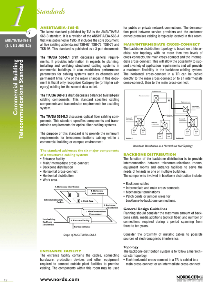
Standards •5 ANSI/TIA/EIA-568-B (B.1, B.2 AND B.3) ANSI/TIA/EIA-568-B The latest standard published by TIA is the ANSI/TIA/EIA 568-B standard. It is a revision of the ANSI/TIA/EIA-568-A that was published in 1995. It includes the core document, all five existing addenda and TSB-67, TSB-72, TSB-75 and TSB-95. This standard is published as a 3-part document: Commercial Building Telecommunications Standard The TIA/EIA 568-B.1 draft discusses general require- ments. It provides information in regards to planning, installing and verifying structured cabling systems in commercial buildings. It also establishes performance parameters for cabling systems such as channels and permanent links. One of the major changes in this document is that it only recognizes Category 5e (or higher category) cabling for the second data outlet. for public or private network connections. The demarcation point between service providers and the customer owned premises cabling is typically located in this room. MAIN/INTERMEDIATE CROSS-CONNECT The backbone distribution topology is based on a hierarchical star topology with no more then two levels of cross-connects, the main cross-connect and the intermediate cross-connect. This will allow the possibility to support a variety of application requirements and will provide a maximum flexibility in the backbone cabling system. The horizontal cross-connect in a TR can be cabled directly to the main cross-connect or to an intermediate cross-connect, then to the main cross-connect. The TIA/EIA 568-B.2 draft discusses balanced twisted-pair cabling components. This standard specifies cabling components and transmission requirements for a cabling system. The TIA/EIA 568-B.3 discusses optical fiber cabling components. This standard specifies components and transmission requirements for optical fiber cabling systems. The purpose of this standard is to provide the minimum requirements for telecommunications cabling within a commercial building or campus environment. Backbone Distribution in a Hierarchical Star Topology The standard addresses the six major components of a structured cabling system: • • • • • • Entrance facility Main/Intermediate cross-connect Backbone distribution Horizontal cross-connect Horizontal distribution Work area. BACKBONE DISTRIBUTION The function of the backbone distribution is to provide interconnection between telecommunications rooms, equipment rooms and entrance facilities to serve the needs of tenants in one or multiple buildings. The components involved in backbone distribution include: • • • • Backbone cables Intermediate and main cross-connects Mechanical terminations Patch cords or jumper wires for backbone-to-backbone connections. General Design Guidelines Planning should consider the maximum amount of backbone cable, media additions (optical fiber) and number of connections required during a period spanning from three to ten years. Scope of ANSI/TIA/EIA-568-B ENTRANCE FACILITY The entrance facility contains the cables, connecting hardware, protection devices and other equipment required to connect outside plant facilities to premise cabling. The components within this room may be used 12 www.nordx.com Consider the proximity of metallic cables to possible sources of electromagnetic interference. Topology The backbone distribution system is to follow a hierarchical star topology. • Each horizontal cross-connect in a TR is cabled to a main cross-connect or an intermediate cross-connect Standards and then a main cross-connect. Systems designed for non-star configurations (ring, bus or tree) can usually be accommodated by the hierarchical star topology. • If special requirements for bus or ring configurations are expected, it is allowable to cable directly between telecommunications rooms • This cabling is in addition to the basic star topology. Recognized Backbone Distribution Media Recognized media may be used individually or in combination. These media are: • 100 Ω UTP cable • 50/125 µm optical fiber cable • 62.5/125 µm optical fiber cable • Singlemode optical fiber cable • 150 Ω STP-A cable. This media is still a recognized media but is not recommended for new installations. Media Selection Criteria The choice of backbone distribution media will depend on the characteristics of specific applications. Factors to consider in making a selection include: • Flexibility with respect to supported services • Required useful life of backbone cable • Site size and user population. In-Building and Inter-Building Backbone Cabling Distances Recommended maximum distances are application and media dependent. It is not assured that all applications will function properly over the specified distances. Note: These maximum backbone distribution distances are the values found in ANSI/TIA/EIA-568-B.1 Standard. HORIZONTAL CROSS-CONNECT The termination of horizontal cable is the primary function of the horizontal cross-connect that is housed in a telecommunications room. Cable of all media types are terminated on compatible connecting hardware. Backbone cable is also terminated on compatible hardware. Connecting hardware, jumper wire and patch cords are collectively referred to as the horizontal cross-connect. Telecommunications Room Functions The primary function is to contain horizontal cable terminations of all recognized types. Recognized types of backbone cable are also terminated here. Cross-connections of horizontal and backbone terminations using jumper wire or patch cords allow for flexibility to extend services to telecommunications outlet/connectors. The intermediate or main cross-connect for portions of the backbone cabling system may also be found in the telecommunications room separate from the horizontal cross-connect. •5 ANSI/TIA/EIA-568-B (B.1, B.2 AND B.3) Commercial Building Telecommunications Standard There cannot be more than two hierarchical levels of cross-connect. • At most, one cross-connect can be passed through to go from the horizontal cross-connect to the main cross-connect • Three or fewer cross-connects can be passed through to go from one horizontal cross-connect to a second horizontal cross-connect. • For high-speed data applications the use of Category 3 or 5e 100 Ω UTP backbone cable shall be limited to a total distance of 90 m (295 ft.) • The capability of single-mode optical may allow for distances up to 60 km (37 miles), however, this is outside the scope of the standard. Cross-connections and Interconnections Moves, add-ons or changes are to be completed by performing cross-connects or interconnects. Cross-connects are connections between horizontal cabling and backbone or equipment connecting hardware. Connections made directly between equipment and horizontal cabling are called interconnects. Maximum backbone distribution distances Media type UTP 62.5/125 µm or 50/125 µm optical fiber Singlemode optical fiber Horizontal Horizontal Main cross-connect cross-connect cross-connect to Main to Intermediate to Intermediate cross-connect cross-connect cross-connect 800 m (2 624 ft.) 2 000 m (6 560 ft.) 300 m (984 ft.) 300 m (984 ft.) 500 m (1 640 ft.) 1 700 m (5 575 ft.) 3 000 m (9 840 ft.) 300 m (984 ft.) 2 700 m (8 855 ft.) Cross-Connection Interconnection www.nordx.com 13 Standards •5 Commercial Building Telecommunications Standard ANSI/TIA/EIA-568-B (B.1, B.2 AND B.3) HORIZONTAL DISTRIBUTION Horizontal distribution is the part of the telecommunications cabling system running from the work area to the horizontal cross-connect in the TR. Horizontal cabling includes: • • • • Horizontal distribution cables Telecommunications outlet/connector in the work area Mechanical termination of the cable media Patch cords/jumper wires in the TR. Note: May also include a multi-user telecommunications outlet assembly (MUTOA) or a consolidation point (CP). General Design Guidelines The horizontal distribution system must satisfy current requirements and should facilitate ongoing maintenance and relocation. Also consider future equipment and service changes. • After installation, horizontal cabling is usually less accessible than other cabling • Horizontal cabling is subject to the greatest amount of activity in the building (approx. 90%) • Consider the diversity of possible services/applications to be used. Consider the proximity of cables to possible sources of electromagnetic interference. Topology The horizontal distribution system must follow a star topology. • The telecommunications outlet/connector in the work area is to be directly connected to a horizontal crossconnect in a telecommunications room located on the same floor as the work area • Bridged taps and splices are not permitted. Distances Regardless of the media type used for horizontal distribution, the maximum distance is 90 m (295 ft.). • This maximum distance is for the amount of cable required to get from the work area outlet to the horizontal cross-connect in the TR • For each horizontal channel a maximum of 10 m (33 ft.) is permitted for work area cords, patch cords, jumper wires and equipment cords (inclusive) • At the horizontal cross-connect the maximum length of patch cords/jumper wires used to connect horizontal cable to equipment or backbone cable is not to exceed 5 m (16 ft.) • It is recommended that the maximum length of cord used in the work area should not exceed 5 m (16 ft.). 14 www.nordx.com Recognized Horizontal Distribution Media Recognized media may be used individually or in combination. These media are: • Four-pair 100 Ω UTP or ScTP cable • 50/125 µm optical fiber cable • 62.5/125 µm optical fiber cable • 150 Ω STP-A cable. This media is still a recognized media but is not recommended for new installations. Hybrid cables (multiple types of media under a single sheath) may be used in the horizontal distribution system if each recognized cable type meets the transmission requirements and color-code specifications for that cable type. • 100 Ω UTP cables of mixed categories are not recommended under the same sheath • Crosstalk specifications between cables of a hybrid cable should be met • It must be possible to distinguish hybrid UTP cables from multi-pair UTP backbone cable • Hybrid cable made up of optical fiber and copper conductors may be referred to as composite cable. Media Selection Criteria Each work area must be equipped with at least two telecommunications outlets/connectors. One outlet may be associated with voice and the other with data. • The first outlet shall be a four-pair 100 Ω cable, Category 3 or higher (Category 5e recommended) • The second outlet shall be one of the following media: - Four-pair 100 Ω Category 5e cable - Two-fiber 50/125 µm optical fiber cable - Two-fiber 62.5/125 µm optical fiber cable. Standards WORK AREA Work area components are from the outlet to the work area equipment. It is assumed a maximum of 5 m (16 ft.) is used for the modular cord at the work area. Four-pair UTP cables are terminated in 8-position modular jacks at the work area. The recommended pin/pair assignment is referred to as T568A-(ISDN). However, if required, T568B-(ALT) can also be used. Copper telecommunications outlet/connector Work area components fall outside the scope of the standard. Work area equipment includes a large variety of equipment. Included are telephones, fax machines, data terminals and computers. Work areas are generally considered to be non-permanent, and are expected to change. Therefore, work areas should be designed to be relatively easy to change. • A special cable or adapter when the equipment connector is different from the outlet/connector • “Y” adapters to permit two services to run on a single cable • Passive adapters used when the horizontal cable type is different from that required by the equipment • Active adapters when connecting devices using different signaling schemes • Adapters allowing pair transposition for compatibility purposes • Termination resistors for ISDN terminals. Consider adapter compatibility with premises cabling and equipment. Adapters may have detrimental effects on the transmission performance of the telecommunications cabling system. Telecommunications Outlet/Connector Pin/pair assignment for 100 Ω UTP cable is recommended to follow the T568A configuration. To accommodate certain cabling systems, the T568B configuration is accepted. U.S. Federal Government publication NCS, FTR 1090-1997 recognizes designation T568A only. 1 W G O BL BR White Green Orange Blue Brown 2 3 W-G G W-O 1 2 3 W-O O W-G 4 5 6 BL W-BL O 4 5 6 BL W-BL G 7 8 W-BR BR 7 •5 ANSI/TIA/EIA-568-B (B.1, B.2 AND B.3) Commercial Building Telecommunications Standard Work area components Some commonly used adapters include the following: Designation T568A 8-position jack pin/pair assignments 8 W-BR BR Designation T568B 8-position jack pin/pair assignments Eight-position jack pin assignments Optical fiber telecommunications outlet/connector The optical fiber cable used in horizontal cabling shall be terminated at the work area with a duplex optical fiber outlet/connector. • The 568SC connector is the recommended connector at the work area • Small form factor connector type may also be considered. Work Area Cords The horizontal distribution system assumes a maximum cord length of 5 m (16 ft.). Cables and connectors should meet or exceed patch cord recommended requirements. Special Adaptations If application specific adaptations such as impedance matching devices are required, they must be external to the telecommunications outlet/connector. www.nordx.com 15 Standards •5 Commercial Building Telecommunications Standard ANSI/TIA/EIA-568-B (B.1, B.2 AND B.3) HORIZONTAL CABLING FOR OPEN OFFICES A horizontal cabling termination point (multi-user telecommunications outlet assembly) and/or intermediate horizontal cabling interconnection point (consolidation point) provide more flexibility in open office layouts with modular furniture, where frequent office rearrangements are performed. Both the multi-user telecommunications outlet assembly and the consolidation point shall be located in a fully accessible, permanent location. Multi-User Telecommunications Outlet Assembly The multi-user telecommunications outlet assembly (MUTOA) is a termination point for the horizontal cabling, consisting of several telecommunications outlets in a common location. The modular line cord extends from the MUTOA to the terminal equipment without any additional intermediate connections. This configuration allows the open office plan to change without affecting the horizontal cabling. Consolidation Point The following guidelines shall be followed when installing a consolidation point; Multi-User Telecommunications Outlet Assembly The following guidelines shall be followed when installing a MUTOA; • The MUTOA shall not be installed in a ceiling • The maximum modular cords length shall be 20 m (66 ft.) • The modular cord connecting the MUTOA to the terminal equipment shall be labeled on both ends with a unique identifier • A MUTOA shall serve a maximum of twelve work areas • The MUTOA shall be marked with the maximum allowable work area cabling (modular cord) length as per the following table: A m (ft.) B m (ft.) C m (ft.) Total Channel m (ft.) 5 (16) 5 (16) 5 (16) 5 (16) 5 (16) 90 (295) 85 (279) 80 (262) 75 (246) 70 (230) 5 (16) 9 (30) 13 (44) 17 (57) 22 (72) 100 (328) 99 (325) 98 (322) 97 (319) 97 (319) Horizontal and Work Area 24 AWG UTP Cabling Lengths 16 Consolidation Point The consolidation point (CP) is an interconnection point within the horizontal cabling. The consolidation point performs a “straight-through” intermediate interconnection between the horizontal cabling coming from the horizontal cross-connect and the horizontal cabling going to a MUTOA or the telecommunications outlet in the work area. Cross-connection between these cables is not allowed. A consolidation point may be useful when reconfiguration is frequent, but not so frequent as to require the flexibility of a MUTOA. www.nordx.com • Ensure that the total channel distance is 100 meters (330 ft.) or less • It is recommended that the consolidation point be located at least 15 m (49 ft.) from the telecommunications room in order to avoid additional NEXT due to short link resonance of multiple connections in close proximity • No more than one consolidation point and one MUTOA shall be used within the same horizontal run • A CP shall serve a maximum of twelve work areas. Standards Permanent Link The permanent Link test configuration represents the permanently installed cabling. It includes: • Up to 90 m (295 ft.) of horizontal cable • Cable from TR to an optional consolidation point and from the consolidation point to the telecommunications outlet • A connection at each end of the horizontal cable. Channel Test Configuration Channel testing is used to verify the performance of the overall channel. The permanent link excludes both the cable portion of the field test instruments cord. Work Area The channel includes the following components: • Up to 90 m (295 ft.) of horizontal cable • Cable between TR and an optional consolidation point and from the consolidation point to the telecommunications outlet • Work area cord • Telecommunications outlet/connector • Cross-connections in the telecommunications room • Patch cord or jumper wire • Telecommunications room equipment cord. G Begin Link F Telecommunications Room Distribution Field of Horizontal Cross-Connect A B Field Tester H Up to 2 meters (6 ft.) End Link F is the horizontal cabling between the telecommunications outlet and the distribution field in the telecomunications room. G and H are test equipment cords that are supplied with the field tester and not taken into consideration in the permanent link test. Work Area Telecommunications Outlet Consolidation point (optional) Up to 2 meters (6 ft.) The total length of equipment cords, patch cords and jumper wires and work area cords is not to exceed 10 m (33 ft.). Field Tester Telecommunications Outlet Field Tester •5 ANSI/TIA/EIA-568-B (B.1, B.2 AND B.3) Commercial Building Telecommunications Standard COPPER CABLING TRANSMISSION PERFORMANCE Transmission performance depends on: • Cable characteristics • Connecting hardware • Patch cords and cross-connect wiring • Number of connections (maximum of four) • Installation and maintenance. Permanent link test configuration Consolidation point Connector Parameters discussed in the document for channel and permanent links are: Begin Channel C Telecommunications Room Cross-Connect between distribution and equipment fields E D End Channel A is Work Area user cord B is a Consolidation Point C is the horizontal Cabling D is the Patch Cord or the Cross-Connect Wire E is the Telecommunications Room Equipment Cord Field Tester • • • • • • • • Insertion loss NEXT loss Power sum NEXT ELFEXT loss Power sum ELFEXT Return loss Propagation delay Delay skew. Channel Test Configuration www.nordx.com 17 Standards •5 Commercial Building Telecommunications Standard ANSI/TIA/EIA-568-B (B.1, B.2 AND B.3) CATEGORY 5 CABLING TRANSMISSION Since the minimum requirement for copper cabling systems is now Category 5e cabling systems; in the ANSI/TIA/ EIA-568-B.1, there is an informative annex that provides cabling transmission performance for Category 5 legacy systems. The important parameters to meet are the Return Loss and the ELFEXT. If an existing Category 5 installation fails either Return Loss or the ELFEXT parameters given in the ANSI/TIA/EIA-568-B.1, annex D, corrective actions should be taken. The document specifies different options to correct the failure. Select the option(s) which is the most appropriate to your situation. • Option 1: Replace the Category 5 patch cord with a Category 5e patch cords. This will possibly correct Return Loss failures. • Option 2: If possible, reconfigure the cross-connect as an interconnect. • Option 3: Replace the Category 5 transition point or consolidation point connector with a Category 5e transition point or consolidation point connector. • Option 4: Replace the Category 5 work area outlet connector with a Category 5e work area outlet connector. • Option 5: Replace the Category 5 interconnect with a Category 5e interconnect. Testing should be performed with an enhanced level II (level II-E) field tester or better. 18 www.nordx.com OPTICAL FIBER CABLING TRANSMISSION PERFORMANCE Minimum recommended performance for a multimode or singlemode optical fiber cabling system are described in this standard. A typical link segment is found between the telecommunications outlet/connector and the horizontal cross-connect. The link segment includes: • Optical fiber cable (length depends on application) • Connectors • Splices. Test Jumper 1 Connector Pair Connector Pair CrossConnect CrossConnect Connector Test Jumper 2 Connector Link configuration The single performance parameter for optical fiber cabling system is the link attenuation. It is the only parameter that can be affected by the installation and can be tested in the field. Depending on the application, a budget loss is allocated for the link segment. Standards telecommunications room. Protective enclosures shall be used when storing slack fibers. Work area connections are extended to the main crossconnect by utilizing either pull-through cables, an interconnect or a splice in the telecommunications room. Use of an interconnection between the horizontal and backbone cabling provides the greatest flexibility, ease of manageability and can easily be migrated to a cross-connect. When sizing backbone cabling, provisions should be The maximum horizontal cabling length is specified at 90 m (295 ft.). The distance of horizontal and backbone cabling combined with work area cords, patch cords and equipment cords is not to exceed 300 m (984 ft.). • Labeling of the centralized cabling system shall follow the requirements as specified in TIA/EIA-606. Centralized cabling systems shall be located within the same building of the work areas being served. All move and change activity shall be performed at the main crossconnect. Horizontal links may be added and removed in the telecommunications room. Horizontal Cable Interconnect Term. Pos. of Splice Pathway Backbone Cable When planning the wall-mount or rack-mount layout, pro- visions should be made to allow future growth. made for future horizontal links thereby minimizing the need for additional backbone cables. The backbone fiber count should be capable of supporting present and future networking technologies. Typically two fibers are required for each application connection required at the work area. • To ensure correct fiber polarity, the centralized cabling system shall implement the A-B orientation at the work area and B-A orientation at the centralized cross-connect as specified in ANSI/TIA/EIA-568-B.1. • Fibers can be joined by either using re-mateable connectors or splices. If connectors are used, the connector shall meet the specifications as defined in ANSI/TIA/EIA-568-B.3. Fibers may be fusion or mechanically spliced, provided the requirements as specified in ANSI/TIA/EIA-568-B.3 are met. •5 ANSI/TIA/EIA-568-B (B.1, B.2 AND B.3) Commercial Building Telecommunications Standard CENTRALIZED OPTICAL FIBER CABLING The purpose of the centralized optical fiber cabling system is to provide a fiber-to-the-desk cabling system utilizing centralized electronics versus the traditional method of distributing the electronics to the individual floors. Work Area Telecommunications Room Pull-through Cable Term. Pos. Backbone Pathway Work Area Term. Pos. Term. Hdwr. Equipment Equipment room When using the pull-through method, the cable is to have a continuous sheath from the work area through the telecommunications room to the centralized crossconnect. The pull-through cable length shall be limited to 300 m (984 ft.). When designing a centralized cabling system, provisions shall be made to allow for the migration from pullthrough, interconnect or splice to a cross-connect implementation. To facilitate this migration, sufficient space shall be left in the telecommunications room for additional patch panels. In addition, adequate cable slack shall be left in the telecommunications room to allow for the cables to be moved to the cross-connect location. Slack can be stored as either cable or unjacketed fibers. When storing slack, provisions shall be made to ensure bend radius limitations are not violated. Cable slack can be stored within an enclosure or on the wall of the NEW PUBLISHED ADDENDA: ANSI/TIA/EIA-568-B.2 addendum 1 This addendum provides the Category 6 requirements for channel and permanent links. The Category 6 cabling systems are part of the ANSI/TIA/EIA 568-B core document and follow all the structured cabling requirements, for example, topology, recognized media type, horizontal and backbone design requirements including the work area. ANSI/TIA/EIA-568-B.2 addendum 2 This addendum is a revision of sub-clause 4.3.4.8, 4.4, 4.4.1, 4.4.4.9 and 5.4.3 of the ANSI/TIA/EIA-568-B.2 document regarding the NEXT parameter equation for category 3 cables. ANSI/TIA/EIA-568-B.2 addendum 3 This addendum is a revision of clause I.2.5 regarding additional considerations for insertion loss and return loss pass/fail determination. ANSI/TIA/EIA-568-B.3 addendum 1 The purpose of this addendum is to provide additional transmission performance specifications for 50/125 µm optical fiber cable capable of supporting 10 Gb/s serial transmission up to 300 m (984 ft.) using 850 nm nominal wavelength lasers. The fiber is called 850 nm LaserOptimized 50/125 µm multimode optical fiber cable. www.nordx.com 19


