************************************************************************** USACE / NAVFAC / AFCEC / NASA ...
advertisement
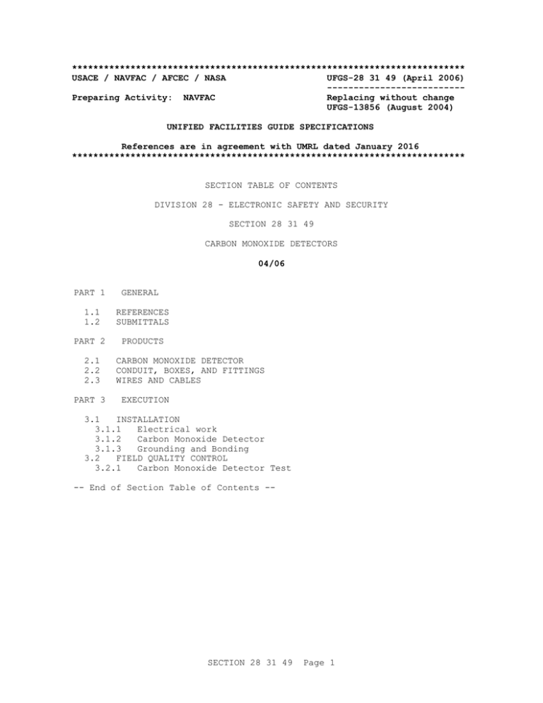
************************************************************************** USACE / NAVFAC / AFCEC / NASA UFGS-28 31 49 (April 2006) -------------------------Preparing Activity: NAVFAC Replacing without change UFGS-13856 (August 2004) UNIFIED FACILITIES GUIDE SPECIFICATIONS References are in agreement with UMRL dated January 2016 ************************************************************************** SECTION TABLE OF CONTENTS DIVISION 28 - ELECTRONIC SAFETY AND SECURITY SECTION 28 31 49 CARBON MONOXIDE DETECTORS 04/06 PART 1 GENERAL 1.1 1.2 REFERENCES SUBMITTALS PART 2 PRODUCTS 2.1 2.2 2.3 PART 3 CARBON MONOXIDE DETECTOR CONDUIT, BOXES, AND FITTINGS WIRES AND CABLES EXECUTION 3.1 INSTALLATION 3.1.1 Electrical work 3.1.2 Carbon Monoxide Detector 3.1.3 Grounding and Bonding 3.2 FIELD QUALITY CONTROL 3.2.1 Carbon Monoxide Detector Test -- End of Section Table of Contents -- SECTION 28 31 49 Page 1 ************************************************************************** USACE / NAVFAC / AFCEC / NASA UFGS-28 31 49 (April 2006) -------------------------Preparing Activity: NAVFAC Replacing without change UFGS-13856 (August 2004) UNIFIED FACILITIES GUIDE SPECIFICATIONS References are in agreement with UMRL dated January 2016 ************************************************************************** SECTION 28 31 49 CARBON MONOXIDE DETECTORS 04/06 ************************************************************************** NOTE: This guide specification covers the requirements for carbon monoxide alarm detectors. Adhere to UFC 1-300-02 Unified Facilities Guide Specifications (UFGS) Format Standard when editing this guide specification or preparing new project specification sections. Edit this guide specification for project specific requirements by adding, deleting, or revising text. For bracketed items, choose applicable items(s) or insert appropriate information. Remove information and requirements not required in respective project, whether or not brackets are present. Comments, suggestions and recommended changes for this guide specification are welcome and should be submitted as a Criteria Change Request (CCR). ************************************************************************** ************************************************************************** NOTE: This guide specification covers carbon monoxide alarm detectors for protection in indoor locations of living quarters where fuel-burning appliances/equipment are used. ************************************************************************** PART 1 1.1 GENERAL REFERENCES ************************************************************************** NOTE: This paragraph is used to list the publications cited in the text of the guide specification. The publications are referred to in the text by basic designation only and listed in this paragraph by organization, designation, date, and title. Use the Reference Wizard's Check Reference feature SECTION 28 31 49 Page 2 when you add a RID outside of the Section's Reference Article to automatically place the reference in the Reference Article. Also use the Reference Wizard's Check Reference feature to update the issue dates. References not used in the text will automatically be deleted from this section of the project specification when you choose to reconcile references in the publish print process. ************************************************************************** The publications listed below form a part of this specification to the extent referenced. The publications are referred to within the text by the basic designation only. NATIONAL FIRE PROTECTION ASSOCIATION (NFPA) NFPA 70 (2014; AMD 1 2013; Errata 1 2013; AMD 2 2013; Errata 2 2013; AMD 3 2014; Errata 3-4 2014; AMD 4-6 2014) National Electrical Code UNDERWRITERS LABORATORIES (UL) UL 2034 1.2 (2008; Reprint Mar 2015) Single and Multiple Station Carbon Monoxide Alarms SUBMITTALS ************************************************************************** NOTE: Review Submittal Description (SD) definitions in Section 01 33 00 SUBMITTAL PROCEDURES and edit the following list to reflect only the submittals required for the project. The Guide Specification technical editors have designated those items that require Government approval, due to their complexity or criticality, with a "G". Generally, other submittal items can be reviewed by the Contractor's Quality Control System. Only add a “G” to an item, if the submittal is sufficiently important or complex in context of the project. For submittals requiring Government approval on Army projects, a code of up to three characters within the submittal tags may be used following the "G" designation to indicate the approving authority. Codes for Army projects using the Resident Management System (RMS) are: "AE" for Architect-Engineer; "DO" for District Office (Engineering Division or other organization in the District Office); "AO" for Area Office; "RO" for Resident Office; and "PO" for Project Office. Codes following the "G" typically are not used for Navy, Air Force, and NASA projects. An "S" following a submittal item indicates that the SECTION 28 31 49 Page 3 submittal is required for the Sustainability Notebook to fulfill federally mandated sustainable requirements in accordance with Section 01 33 29 SUSTAINABILITY REPORTING. Choose the first bracketed item for Navy, Air Force and NASA projects, or choose the second bracketed item for Army projects. ************************************************************************** Government approval is required for submittals with a "G" designation; submittals not having a "G" designation are [for Contractor Quality Control approval.][for information only. When used, a designation following the "G" designation identifies the office that will review the submittal for the Government.] Submittals with an "S" are for inclusion in the Sustainability Notebook, in conformance to Section 01 33 29 SUSTAINABILITY REPORTING. Submit the following in accordance with Section 01 33 00 SUBMITTAL PROCEDURES: SD-03 Product Data Carbon monoxide detector SD-06 Test Reports Carbon monoxide detector test [ SD-10 Operation and Maintenance Data Carbon monoxide detector; Data Package 1 Submit in accordance with Section 01 78 23 OPERATION AND MAINTENANCE DATA.] PART 2 2.1 PRODUCTS CARBON MONOXIDE DETECTOR UL 2034, [Single station] [Multiple station] detector [surface] [flush] mounted. Operational requirements shall be as follows: a. Electrical: [120 Volt AC with 9 volt battery backup] [_____] volt DC b. Environmental: 0 degrees to 49 degrees C 32 degrees to 120 degrees F. ************************************************************************** NOTE: Corps of Engineers EM 385-1-1, Safety and Health Requirements Manual has specified that air shall not contain a level of carbon monoxide greater than 20 ppm. ************************************************************************** c. Alarm and Indicator: Red LED for visual and 85 db at [3050] [_____] mm [10][_____] ft for audible alarm. Malfunction indicator light shall be yellow or amber LED. Power on indicator light shall be white or green for 120 Volt AC powered units, while operating on AC power. d. Alarm reset/silence button: Provide a manually operated alarm reset and silence button. Pressing the button shall silence the alarm, and SECTION 28 31 49 Page 4 reset the detector. Alarm shall resound within 6 minutes if CO level remains at or above 70 ppm. e. 2.2 Battery removal flag: Provide a warning flag that will be exposed while the battery is removed, and hidden while the battery is installed. CONDUIT, BOXES, AND FITTINGS ************************************************************************** NOTE: The second bracketed option is the short form version of the interior electrical and its use is at the discretion of the Engineer/Architect in charge. ************************************************************************** Specified in Section 26 20 00 INTERIOR DISTRIBUTION SYSTEM. 2.3 WIRES AND CABLES ************************************************************************** NOTE: The second bracketed option is the short form version of the interior electrical and its use is at the discretion of the Engineer/Architect in charge. ************************************************************************** Specified in Section 26 20 00 INTERIOR DISTRIBUTION SYSTEM. PART 3 3.1 3.1.1 EXECUTION INSTALLATION Electrical work Electrical installation shall conform to the requirements of Section 26 20 00 INTERIOR DISTRIBUTION SYSTEM and NFPA 70. 3.1.2 Carbon Monoxide Detector Install detector[s] in accordance with the manufacturer's instructions. Provide detector in hallway outside bedroom[s], [_____], and in location[s] as indicated. 3.1.3 Grounding and Bonding Equipment grounding and bonding shall be in accordance with UL 2034 and NFPA 70. 3.2 FIELD QUALITY CONTROL Provide test equipment and personnel and submit written copies of the test results. Notify Contracting Officer [15] [_____] working days prior to the test. 3.2.1 Carbon Monoxide Detector Test Contractor shall show by demonstration in service that the detector[s] SECTION 28 31 49 Page 5 [is][are] in good condition and properly performing the intended function. Test shall be in accordance with UL 2034 requirements specified in paragraph entitled "Normal Operation Test" [and the manufacturer's test procedure]. -- End of Section -- SECTION 28 31 49 Page 6
