************************************************************************** USACE / NAVFAC / AFCEC / NASA ...
advertisement
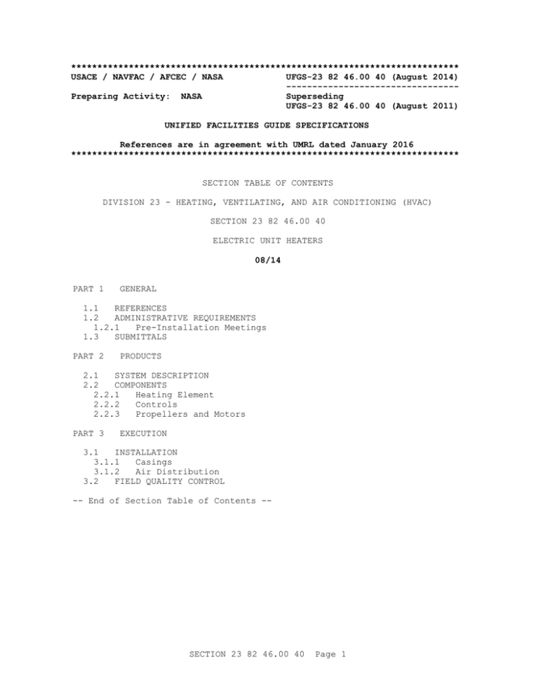
************************************************************************** USACE / NAVFAC / AFCEC / NASA UFGS-23 82 46.00 40 (August 2014) --------------------------------Preparing Activity: NASA Superseding UFGS-23 82 46.00 40 (August 2011) UNIFIED FACILITIES GUIDE SPECIFICATIONS References are in agreement with UMRL dated January 2016 ************************************************************************** SECTION TABLE OF CONTENTS DIVISION 23 - HEATING, VENTILATING, AND AIR CONDITIONING (HVAC) SECTION 23 82 46.00 40 ELECTRIC UNIT HEATERS 08/14 PART 1 GENERAL 1.1 REFERENCES 1.2 ADMINISTRATIVE REQUIREMENTS 1.2.1 Pre-Installation Meetings 1.3 SUBMITTALS PART 2 PRODUCTS 2.1 SYSTEM DESCRIPTION 2.2 COMPONENTS 2.2.1 Heating Element 2.2.2 Controls 2.2.3 Propellers and Motors PART 3 EXECUTION 3.1 INSTALLATION 3.1.1 Casings 3.1.2 Air Distribution 3.2 FIELD QUALITY CONTROL -- End of Section Table of Contents -- SECTION 23 82 46.00 40 Page 1 ************************************************************************** USACE / NAVFAC / AFCEC / NASA UFGS-23 82 46.00 40 (August 2014) --------------------------------Preparing Activity: NASA Superseding UFGS-23 82 46.00 40 (August 2011) UNIFIED FACILITIES GUIDE SPECIFICATIONS References are in agreement with UMRL dated January 2016 ************************************************************************** SECTION 23 82 46.00 40 ELECTRIC UNIT HEATERS 08/14 ************************************************************************** NOTE: This guide specification covers the requirements for electric unit heaters. Indicate on drawings the capacity, voltage, rating, control-circuit voltage, cfm, sizes, mounting height, and other pertinent data. Adhere to UFC 1-300-02 Unified Facilities Guide Specifications (UFGS) Format Standard when editing this guide specification or preparing new project specification sections. Edit this guide specification for project specific requirements by adding, deleting, or revising text. For bracketed items, choose applicable items(s) or insert appropriate information. Remove information and requirements not required in respective project, whether or not brackets are present. Comments, suggestions and recommended changes for this guide specification are welcome and should be submitted as a Criteria Change Request (CCR). ************************************************************************** PART 1 1.1 GENERAL REFERENCES ************************************************************************** NOTE: This paragraph is used to list the publications cited in the text of the guide specification. The publications are referred to in the text by basic designation only and listed in this paragraph by organization, designation, date, and title. Use the Reference Wizard's Check Reference feature when you add a RID outside of the Section's Reference Article to automatically place the reference in the Reference Article. Also use the Reference Wizard's Check Reference feature to update SECTION 23 82 46.00 40 Page 2 the issue dates. References not used in the text will automatically be deleted from this section of the project specification when you choose to reconcile references in the publish print process. ************************************************************************** The publications listed below form a part of this specification to the extent referenced. The publications are referred to within the text by the basic designation only. UNDERWRITERS LABORATORIES (UL) UL 1996 1.2 (2009; Reprint Jun 2014) Electric Duct Heaters ADMINISTRATIVE REQUIREMENTS ************************************************************************** NOTE: If Section 26 00 00.00 20 BASIC ELECTRICAL MATERIALS AND METHODS is not included in the project specification, applicable requirements therefrom should be inserted and the following paragraph deleted. ************************************************************************** Section 26 00 00.00 20 BASIC ELECTRICAL MATERIALS AND METHODS applies to work specified in this section. 1.2.1 Pre-Installation Meetings The Contracting Officer will schedule a pre-installation meeting within [30] [_____] days of Contract Award. Provide the following for review and approval: a. Submit fabrication drawings for electric heaters indicating the of fabrication and assembly details to be performed in the factory. b. Submit equipment and performance data for electric heaters life, test, system functional flows, safety features, and mechanical automated details. c. Submit manufacturer's instructions for electric heaters stating the special provisions required to install equipment components and system packages. Detail impedances, hazards and safety precautions within the special notices. 1.3 SUBMITTALS ************************************************************************** NOTE: Review Submittal Description (SD) definitions in Section 01 33 00 SUBMITTAL PROCEDURES and edit the following list to reflect only the submittals required for the project. The Guide Specification technical editors have designated those items that require Government approval, due to their complexity or criticality, SECTION 23 82 46.00 40 Page 3 with a "G." Generally, other submittal items can be reviewed by the Contractor's Quality Control System. Only add a “G” to an item, if the submittal is sufficiently important or complex in context of the project. For submittals requiring Government approval on Army projects, a code of up to three characters within the submittal tags may be used following the "G" designation to indicate the approving authority. Codes for Army projects using the Resident Management System (RMS) are: "AE" for Architect-Engineer; "DO" for District Office (Engineering Division or other organization in the District Office); "AO" for Area Office; "RO" for Resident Office; and "PO" for Project Office. Codes following the "G" typically are not used for Navy, Air Force, and NASA projects. An "S" following a submittal item indicates that the submittal is required for the Sustainability Notebook to fulfill federally mandated sustainable requirements in accordance with Section 01 33 29 SUSTAINABILITY REPORTING. Choose the first bracketed item for Navy, Air Force and NASA projects, or choose the second bracketed item for Army projects. ************************************************************************** Government approval is required for submittals with a "G" designation; submittals not having a "G" designation are [for Contractor Quality Control approval.][for information only. When used, a designation following the "G" designation identifies the office that will review the submittal for the Government.] Submittals with an "S" are for inclusion in the Sustainability Notebook, in conformance to Section 01 33 29 SUSTAINABILITY REPORTING. Submit the following in accordance with Section 01 33 00 SUBMITTAL PROCEDURES: SD-02 Shop Drawings Fabrication Drawings[; G[, [____]]] SD-03 Product Data Equipment and Performance Data[; G[, [____]]] Electric Unit Heaters[; G[, [____]]] Heating Element[; G[, [____]]] Controls[; G[, [____]]] Casings[; G[, [____]]] Propellers and Motors[; G[, [____]]] SD-08 Manufacturer's Instructions SECTION 23 82 46.00 40 Page 4 Manufacturer's Instructions[; G[, [____]]] PART 2 2.1 PRODUCTS SYSTEM DESCRIPTION Provide suspended electric unit heaters and arrange for discharge of air as indicated. Provide electric unit heaters with not less than the indicated capacity and conform to requirements specified herein. Ensure electric unit heaters are factory prewired, ready for field terminal connections. Ensure products conform to the requirements of UL 1996 for electric unit heaters. 2.2 2.2.1 COMPONENTS Heating Element Construct heating element of a resistance wire insulated by highly compacted refractory insulation protected by a sealed metallic-finned sheath. Component materials are as follows: a. Provide resistance wire not less than 20-helix wound alloy approximately 80-percent nickel and 20-percent chromium. b. Provide refractory insulation of magnesium oxide with a resistance of not less than 50,000-ohms after exposure to an ambient temperature and humidity of 32 degrees C 90 degrees F and 85 plus or minus 5-percent relative humidity, respectively, for not less than 24 hours. c. Provide sheathing consisting of aluminum fins cast around an internal steel sheath containing refractory insulation and resistance wire or carbon-steel fins permanently attached to a tubular carbon-steel sheath containing refractory insulation and resistance wire and with external surfaces porcelainized. [ Ensure maximum surface temperature of porcelain-protected steel sheathing is [ 370] [_____] degrees C [700] [_____] degrees F. ][Ensure maximum surface temperature of cast-aluminum sheathing is [260] [_____] degrees C [500] [_____] degrees F. ]2.2.2 Controls [ Fit units up to and including 5 kilowatts with integral controls including thermal overload cutout switches, necessary transformers, liquid-vapor system, and low-mass bimetal thermostat as required. Provide cutout switch that can be automatically reset. ][Provide unit with conductors in the including thermal transformers, and switches that can a remote unfused disconnect switch that opens ungrounded OFF position and a thermostat with integral controls overload cutout switches, magnetic contactors, necessary thermostat protection as required. Provide cutout be automatically reset. ] Provide wall-mounted thermostats complete with thermometer, mechanical high-limit stop, calibrated operator, and an adjustable heater to effect SECTION 23 82 46.00 40 Page 5 anticipation and to prevent override of space temperature with a range between 12 and 41 degrees C 55 and 105 degrees F and a differential not exceeding 1 degrees C 1.5 degrees F. Provide thermostat rated for operation at 24 volts, 60 hertz. Provide transformers, wiring, and devices necessary to meet this requirement. Finish cases in brushed or satin chrome. 2.2.3 Propellers and Motors Provide propellers with[ mill-aluminized][ galvanized-steel][ all-aluminum blades] statically and dynamically balanced to within 0.5 percent. Provide units with fan-inlet safety guards. AMCA certify propellers and motors for air performance and noise level. Protect motors against damage by the heating element and resilient mount. Conform to Section 26 60 13.00 40 LOW-VOLTAGE MOTORS for motors, except that load-matched and custom-designed motors may be used and be so identified on the shop drawings. For motors not so identified conform to the requirements specified. Subfractional and fractional custom-designed or applied motors may deviate from the preceding motor requirements as follows: a. Shaded-pole motors rated less than 125 watt 1/6-horsepower may be used for direct-drive service. b. Permanent split-capacitor, split-phase, and capacitor-start motors rated 185 watt 1/4-horsepower and less may be used for direct-drive service. c. Split-phase and capacitor-start motors, rated 185 watt 1/4-horsepower and less, may be used for belt-drive service. d. Motor bearings may be manufacturer's standard prelubricated sleeve type except provide motor with antifriction thrust bearings, when specified. Ensure lubricant provisions are extended service type, requiring replenishment not more than twice per year of continuous operation. Provide motor identification plate per manufacturer's standard. Provide motor speed and control per unit-heater manufacturer's standard. PART 3 3.1 EXECUTION INSTALLATION Install unit heaters in accordance with the manufacturer's instructions at the mounting heights indicated. 3.1.1 Casings Provide casings with smoothly contoured propeller orifice rings of not less than 1.0 millimeter 20-gage cold-rolled carbon steel. Provide casing surface finish with phosphate pretreatment, prime coating, and baked-enamel finish. SECTION 23 82 46.00 40 Page 6 3.1.2 Air Distribution [ Fit vertical discharge units with louver-cone diffusers. ][Provide horizontal units with adjustable single- or double-deflection louvers. ]3.2 FIELD QUALITY CONTROL Demonstrate in the presence of the Contracting Officer that the unit heaters operate satisfactorily. Cycle unit heaters five times, from start to operating thermal conditions to off, to verify adequacy of construction, system controls, and component performance. Conduct an operational test for a minimum of 6 hours. -- End of Section -- SECTION 23 82 46.00 40 Page 7
