Demonstration of Autonomous Rendezvous Technology (DART) Inter-Agency AR&C Working Group May 22-23, 2002
advertisement
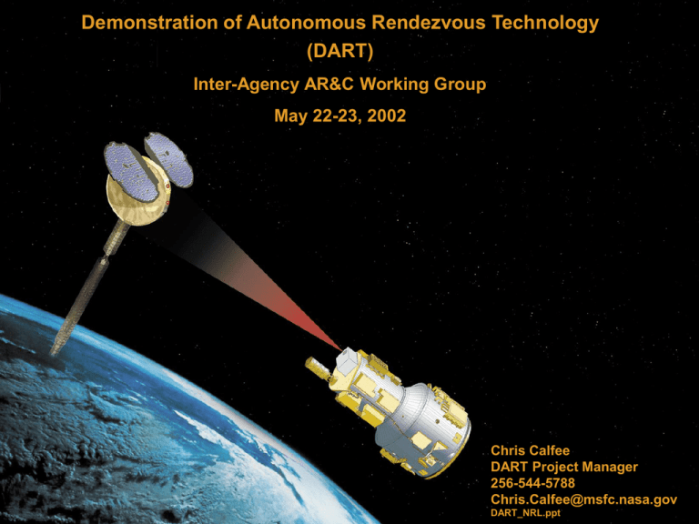
Demonstration of Autonomous Rendezvous Technology (DART) Inter-Agency AR&C Working Group May 22-23, 2002 Chris Calfee DART Project Manager 256-544-5788 Chris.Calfee@msfc.nasa.gov 1 DART_NRL.ppt DART_NRL.ppt Agenda – Introduction to DART • Overview & Objectives • Organization & Schedule – DART Mission Description • “Chaser” Vehicle - DART • “Target” Vehicle - MUBLCOM • Launch Vehicle - Pegasus • Mission Operations - Flight & Ground • System Test Summary • Technology Readiness Levels – Advanced Video Guidance Sensor (AVGS) 2 DART_NRL.ppt Introduction to DART 3 DART_NRL.ppt Project Overview • DART Stands for: Demonstration of Autonomous Rendezvous Technology. • DART Is a Flight Demonstration of the Hardware and Software Required to Autonomously Rendezvous with a Satellite (MUBLCOM) Currently in Orbit. – Hardware: Advanced Video Guidance Sensor (AVGS) • Heritage: VGS Developed by MSFC for Automated Rendezvous & Capture (AR&C) Project. Flown Twice on Board the Shuttle in an OpenLoop Mode • AVGS is next generation system with advanced optics and electronics. Design goals: Longer Range, Lower Power and Weight – Software: Based on Autonomous Rendezvous and Proximity Operations (ARPO) Algorithms Also Developed by NASA/MSFC. • Both the AVGS and the ARPO Algorithms Will Become Embedded Technology on Board a Pegasus ELV, Making the DART Vehicle an Extension of the ELV Rather Than an Independent and Isolated Payload 4 DART_NRL.ppt DART Objectives Primary Objective: Demonstrate in space Autonomous Rendezvous and Closed Loop Proximity Control Between a Chase Vehicle, DART, and a Passive, Cooperative Target Vehicle, MUBLCOM • Raise AVGS/ARPO Technology Readiness Levels (TRL) from a 3/4 to a 7/8 • Validate Ground Test Results of the AVGS and ARPO Algorithms • Mission Objectives – Transfer from parking orbit to MUBLCOM orbit – Demonstrate Autonomous Proximity Operations While In the Vicinity of the Target Vehicle Using The AVGS • V-Bar Approach and Stand-Off to 15 meters • Collision Avoidance Maneuver (CAM) • Docking Axis Approach and Stand-Off to 5 meters • R-Bar Approach and Stand-Off to 50 Meters • Autonomous Departure at End Of Mission 5 DART_NRL.ppt Second Generation RLV Relevance – The United States Has Successfully Performed Numerous Rendezvous and Docking Missions in the Past. – The Common Element of All US Rendezvous and Docking is That the Spacecraft Have Always Been Piloted by Astronauts. – Only the Russian Space Program Has Developed and Demonstrated a Routine Autonomous Capability. – The European Space Agency and Japanese Are Developing Similar Technology. – The DART Mission Provides a Key Step in Establishing an Autonomous Rendezvous Capability for the United States. – All 2nd Generation Architectures and AAS Can Benefit From ARPO Technology. – Even Manned/Piloted Vehicles Can Benefit Through Robust System Performance and Reduction of Potential Piloting Errors. 6 DART_NRL.ppt DART Project Overview Schedule 7 DART_NRL.ppt Project Team – OSC - Overall Project Integration, Launch Vehicle Buildup & Test, AVGS Development, Test, Manufacture, & Integration, DART Buildup & Test, LV/DART Integration & Test, Launch & Mission Operations – MSFC - Overall Project Management, AR&C Algorithms, AVGS S/W Development, Test Facilities & Support, Mission ops Support – Draper – GNC System, Flight Vehicle S/W – Advanced Optical Systems (AOS) - AVGS Design & Engineering Support – KSC - Launch Services Support – GSFC - IV&V 8 DART_NRL.ppt 2nd Generation RLV Organization Program Office Consultants E.G. F. Wojtalik, G. Oliver, B. Lindstrom Ext. Rqmts. Assessment Team Manager Dennis Smith Deputy Dan Dumbacher Quality Assurance Man. C. Chesser Chief Engineer Robert Hughes Tech. Asst. B. Morris ESA Jill Holland MSA Judy Dunn Program Planning and Control Sys. Engineering, & Integration Rose Allen, Manager Jerry Cook, Deputy Dale Thomas, Manager Chuck Smith, Deputy Airframe (LaRC) Operations (KSC) Flight Mechanics (MSFC) Manager D. Bowles LSE Julie Fowler Manager Scott Huzar LSE Manager Scott Jackson LSE Jack Mulqueen Procurement Legal M. Stiles J. Seemann Program Integration & Risk Management Architecture Definition Danny Davis, Manager Bart Graham, Deputy Steve Creech, Manager Arch. Mgr. Arch. Mgr Arch. Mgr CTV AAS Bob Armstrong Charlie Dill Pete Rodriguez Steve Davis Chris Crumbly NASA Unique (JSC) Manager LSE Dave Leestma Subsystems (GRC) Manager LSE Mike Skor Tom Hill IVHM (ARC) Manager Bill Kahle Asst. Mgr./LSE Kevin Flynn Flt. Demos & Exp. Integ. (MSFC) Propulsion (MSFC) Manager Garry Lyles Dep. Mgr. Steve Richards Lead Sys. Engr. George Young Manager, acting Deputy 9 Susan Turner DART_NRL.ppt Flight Demos & Experiment Integration Organization Flt. Demos & Exp. Integ. Susan Turner X-37 DART Kistler K-1 Jeff Sexton Chris Calfee Jimmy Lee 10 DART_NRL.ppt DART Organization 2nd Generation RLV Program Dennis Smith, Manager Flt. Demos & Exp. Integ. Susan Turner, Manager Contracts Earl Pendley Penny Battles Carol Greenwood DART Chris Calfee, Manager Pegasus Procurement S&MA Van Strickland Marcie Kennedy Wanda Harding - KSC Business Jimmy Black Rich Leonard Louise Hamaker Asst. DART Manager Dexter Waldrep Lead Systems Engineer Lead Software Engineer AVGS/Pegasus Lead Engineer Mark Krome Meg Stroud 11 Keith Higginbotham DART_NRL.ppt OSC DART Organization Chart 12 DART_NRL.ppt DART Mission Description 13 DART_NRL.ppt Mission Overview Description of DART Vehicle Pegasus Stage 4 / HAPS • Hydrazine Auxiliary Propulsion System (HAPS) – – 3 thrusters with 56.9 Kg (125 lbm) supply Delta-velocity, pitch and yaw attitude • Pegasus Reaction Control System – – Ybody 6 nitrogen thrusters with dedicated 5.8 Kg (13 lbm) supply 3-axis attitude control during rendezvous and retirement Zbody • Proximity Operations Reaction Control System – – 16 N2 thrusters with dedicated 29 kg (64 lbm) Tank 6-axis attitude and translational control during proximity operations • Lithium Ion Battery Powered Avionics and Transient Power Busses • UHF Antenna & Receiver System • SIGI INS and Standalone GPS Navigation Solution AVGS Bus • Advance Video Guidance Sensor • Maximum wet mass: 362.3 Kg (798 lbm) – Assuming Pegasus XL launch to 500 km orbit at 97.7° inclination 14 DART_NRL.ppt DART Mechanical Configuration • Within Pegasus Stage 4 Avionics Structure is Top of HAPS Tank, Two RCS Tanks, SIGI – Mostly Heritage Components and Layout for Stage 4 Pegasus Stage 4 • Within AVGS Bus Structure is Top of Proximity Ops RCS Tank – Most New Components Mounted to Exterior of Cylindrical Structure, Forward AVGS Panel AVGS Bus DART Expanded View Forward Looking Aft 15 DART_NRL.ppt DART Mechanical Configuration, Cont MACH Batteries Proximity Ops RCS Tank, Tubing, Other Components HAPS Tank, Tubing, and Other Components DART Expanded View Aft Looking Forward 16 DART_NRL.ppt Description of MUBLCOM Target Vehicle FAR RANGE GROUP • Launched in 1999 aboard a Pegasus Rocket • Currently in a nearly circular orbit at 765 km • Near-polar orbit with 97.7 inclination (nearly sun-synchronous) • Gravity-gradient stabilized with momentum wheels for yaw control • Long and short-range retroreflectors mounted ~parallel to velocity vector • Far-range retroreflectors mounted along vehicle z-axis (nadir pointing) 17 DART_NRL.ppt MUBLCOM 18 DART_NRL.ppt Expanded View of Pegasus w/DART 19 DART_NRL.ppt Mission Overview DART Launch Operations Overview • Pegasus launch from Vandenburg AFB, CA on 4/15/04 • Launch will deliver DART to a circular orbit at 500 Km altitude • Ascending node and inclination matching those of the MUBLCOM satellite • Hydrazine budgeted to allow Pegasus use of HAPS to correct launch dispersions t=0 h = 11887 m v = 243 m/sec • ±30 second drop window assumed – Minimizes ascending node errors – Drop position accuracy relaxed to allow better drop time accuracy • Launch opportunity every 3-5 days – Phasing with MUBLCOM at launch constrained to less than 100° 20 DART_NRL.ppt Mission Overview DART Rendezvous Operations Overview 40 km • Early orbit checkout Phasing Orbit 1 Phasing Orbit 2 Target Orbit DART Trajectory C • DART “catches up” to target vehicle at ~13 deg/hour – Up to 7.5 hours spent in Phasing orbit 1 3 km A E • Hohmann transfer from 500 Km to ~755 Km altitude D B – Rendezvous ends with DART 40 Km behind and 7.5 Km beneath MUBLCOM A. Insertion into phasing orbit 1 B. Begin transfer to phasing orbit 2 C. Insertion into phasing orbit 2 D. Begin transfer to target orbit E. Insertion into target orbit • Rendezvous algorithms employ Pegasus PEG guidance – PEG functionality extended with rendezvous phasing calculations • Ascending node and inclination errors corrected during transfer using HAPS 21 DART_NRL.ppt Mission Overview DART DRM Timeline Event Drop From Aircraft Stage 3 Separation Pegasus HAPS Burn (nominally not required) Begin Early Orbit Checkout Begin Haps Transfer Burn For Rendezvous Start Haps Out-Of-Plane Correction Burn MUBLCOM UHF Signal Acquisition Begin Haps Burn For Rendezvous Insertion Start Proximity Operations GN&C Begin CW Transfer To -3 Km On -V Bar AVGS To Standby Mode Insertion At -3 Km On -V Bar AVGS To Spot Mode Insertion At -1 KM On -V Bar AVGS to Acquisition Mode Station Keep At -300 M Station Keep At -15 M Station Keep At -100 M Station Keep At -300 M Depart To Maximum AVGS Tracking Range Begin Forced Motion Return To -300 M Station Keep At -300 M Begin CW Transfer To 150 M On R Bar AVGS To Spot Mode Station Keep At 150 M On R Bar Station Keep At 50 M On R Bar Station Keep At 300 M On R Bar AVGS Off Start Retirement Burn End of 24 Hour Mission Time from Drop (Hours) 00:00:00 00:08:58 00:09:00 00:20:00 07:25:41 07:40:46 07:55:45 08:08:36 08:10:50 08:37:39 08:37:39 09:28:34 09:33:34 10:51:32 11:23:20 11:31:32 11:52:33 13:27:28 14:08:49 14:13:49 14:25:08 14:36:46 15:06:46 15:32:42 15:32:42 16:08:38 16:26:52 16:33:52 16:33:52 24:00:00 22 • Worst-case phasing at launch assumed – 7+ hours in phasing orbit 1 • Proximity operations begin 8 hours into the mission – 8 hours in proximity operations – Includes 3.5 hours of station keeping at various positions • Retirement burn 16.5 hours into mission – 7.5 hour time margin remaining DART_NRL.ppt DART Mission Profile GPS State Vector Differencing (Propagated Target State) Communications Range (~100 km) 770 Altitude(km) Proximity Sensor (AVGS) GPS State Vector Differencing (Space-to-Space Target State) Visible Range (~500 m) -3km Target Vehicle 755 Orbit Transfer Free Drift Start of Proximity Operations DART Retirement Burn Phasing 500 Launch Ascent Far Range MET From L1011 Drop 00:09:00 Mid Range 08:00:00 Near Range 11:00:00 16:30:00 Note: Altitude and Ranges are not to scale 23 DART_NRL.ppt DART Proximity Operations Flight Profile Velocity Vector Orbital Motion +VBar MUBLCOM 50 m 5m 300 m 15 m 100 m CAM 1 Km 3 Km 500 m 150 m Last HAPS Burn 40 Km behind 7.5 Km below End of Rendezvous Start of Prox Ops 300 m Baseline Profile Extended Profile +RBar Retirement Burn Free Drift Orbit Transfer 24 DART_NRL.ppt DART-MUBLCOM Rendezvous Visual QuickTime™ and a decompressor are needed to see this picture. 25 DART_NRL.ppt Mission Overview DART DRM Ground Station Coverage • Three ground stations selected for telemetry coverage (VAFB for launch only) – Poker Flats, Alaska – McMurdo, Antarctica – Svalbard, Norway • Polar stations provide at least two telemetry downlink opportunities per orbit 26 DART_NRL.ppt DART Testing • Desktop Simulation – Performed at OSC – Psuedo Flight Code (CMDH, GN&C,Telemetry) • Hardware in the Loop – Static – Performed at OSC – Flight Computer, GPS, INS, UHF, AVGS • Hardware in the Loop – Dynamic – Performed at MSFC Flight Robotics Lab – Flight Computer, GPS, INS, AVGS 27 DART_NRL.ppt Addressing SLI Program Goals: Increasing Technology Readiness Level TRL Level Start: AVGS and ARPO at TRL 4 Finish: AVGS and ARPO at TRL 7/8 Description Summary 1 Basic principles observed and reported 2 Technology concept and/or application formulated 3 Analytical and experimental critical function and/or characteristic proofof-concept 4 Component and/or breadboard validation in laboratory environment 5 Component and/or breadboard validation in relevant environment 6 System/subsystem model or prototype demonstration in a relevant environment (ground or space) 7 System prototype demonstration in a space environment 8 Actual system completed and “flight qualified” through test and demonstration (ground or flight) 9 Actual system “flight proven” through successful mission operations Addressing SLI Program Goals: ARPO Technology Readiness Levels 29 DART_NRL.ppt Advanced Video Guidance Sensor (AVGS) 30 DART_NRL.ppt OLD VGS SENSOR (HEAD AND ELECTRONIC MODULE) 31 DART_NRL.ppt Proximity Sensor Comparison to Flight proven Unit VGS Optics 8 lasers AVGS 4 lasers (reduced complexity and power) Laser not in optical path Lasers in optical path (Increased laser return) Camera Electronics Analog Camera Digital CMOS Camera (resolution 640 X 480) (resolution 1000 X 1000) 5 Hz update 50 Hz update 2 boxes (50 lbs total) Single box (20 lbs) (10” X 12” X 8”) Performance Signal processing in separate VME Single DSP board in sensor box 60 watts power 8 watts power 150 m range 1-5 km range (spot mode) 300-500 m (full 6DOF) (Range & Target Specific) +/-0.30 cm position, accuracy +/-0.12 mm position, accuracy +/-0.30 cm/s velocity, accuracy +/-0.10 mm/s velocity, accuracy +/-0.25 deg attitude, accuracy +/-0.10 deg attitude, accuracy 32 DART_NRL.ppt AVGS Functional Flow From “On-Orbit Testing of the Video Guidance Sensor” by Richard T. Howard, Thomas C Bryan, Michael L. Book, NASA/MSFC 33 DART_NRL.ppt AVGS Design, Analysis and Test – Brassboard Development Phase (6/1/01 - 1/28/02) • Parts and Material Review – EEE Parts Availability – Outgasssing – Radiation Environment Analysis • Begin AVGS Software Development • Evaluate Optics Performance – Initial Prototype (IP) Development Phase (6/1/01 - 3/29/02) • Power Supply Design • Electronics Packaging Concepts • Initial Structural Analysis • Initial Electrical Analysis • Initial Thermal Analysis • Radiation Hardening • Continue AVGS Software Development 34 DART_NRL.ppt AVGS Design, Analysis and Test (Cont) – Final Prototype (FP) Development Phase (4/1/02 - 10/18/02) • 2 Prototype Units (Form, Fit & Function) • FMEA • Update Thermal Analysis • Finalize Electronic Packaging Concepts • Final Design for Radiation Environment • Finalize Structural Analysis • Finalize Electrical Analysis • Begin AVGS Software functional Verification and Validation – Qualification Unit Development Phase (9/23/02 - 5/29/03) • Acceptance Testing (random vibe and thermal vac) • Qualification Testing (EMI/EMC, Vibe, Shock, Thermal) • AVGS Flight Load Software Delivery – Flight Unit Development Phase (5/1/03 - 11/17/03) • 3 Units • Acceptance Testing (random vibe and thermal vac) • Final AVGS Software Load Delivery (Jan04) 35 DART_NRL.ppt New AVGS Initial Proto-Type Unit 36 DART_NRL.ppt AVGS Development Breadboard Sensor Optics 37 DART_NRL.ppt Addressing SLI Program Goals: DART-AVGS Technology Readiness Levels 38 DART_NRL.ppt DART POP02 Summary by Center NOA $K FY01 FY02 FY03 FY04 Totals Actual RQMT OGL/UGL RQMT OGL/UGL RQMT OGL/UGL RQMT OGL/UGL MSFC Subtotal 9,502 8,105 GSFC Subtotal 0 69 0 6,111 5,940 0 KSC Subtotal - Pegasus Total DART 15,613 14,114 0 11,736 3,654 4,697 512 135 2,096 -5,527 710 -591 34,040 914 647 7,806 6,027 21,953 500 0 14,542 -1,361 12,638 5,571 56,907 4,209 39 135 3,062 DART_NRL.ppt Automated Rendezvous and Capture Documentation Technical Publications http://alternate.msfc.nasa.gov/AR&C/ a. Application of Neural Networks to Autonomous Rendezvous and Docking of Space Vehicles, Richard W. Dabney, AIAA Paper 92-1516, AIAA Space Programs and Technologies Conference, March 24-27, 1992, Huntsville, AL. b. United States Patent Number 5,109,345, CLOSED-LOOP AUTONOMOUS DOCKING SYSTEM, Richard W. Dabney and Richard T. Howard, April 28, 1992. c. A Plan for Spacecraft Automated Rendezvous, A. W. Deaton, J. J. Lomas, and L. D. Mullins, NASA TM-108385, October 1992. d. Guidance and Targeting Simulation for Automated Rendezvous, James J. Lomas, John M. Hanson, and M. Wade Shrader, AAS Paper 94-162, AAS/AIAA Spaceflight Mechanics Meeting, February 14 - 16, 1994, Cocoa Beach, FL. e. Guidance Schemes for Automated Terminal Rendezvous, John M. Hanson and Alva W. Deaton, AAS Paper 94-163, AAS/AIAA Spaceflight Mechanics Meeting, February 14 - 16, 1994, Cocoa Beach, FL. f. A Solution to the 3 Point Inverse Perspective Problem for Automated Rendezvous and Capture, Richard Dabney and Philip Calhoun, MSFC Memorandum ED13-9421, September 30, 1994. g. Cargo Transfer Vehicle (CTV) Reference Design for Autonomous Rendezvous and Capture Simulations, Richard Dabney, MSFC Memorandum ED13-94-22 , October 26, 1994. h. MSFC-RQMT-2371 B, Automated Rendezvous and Capture (AR&C) System Requirements Document (SRD), Craig A. Cruzen, July 1, 1996. i. MSFC Flight Robotics Laboratory (FRL) Description, A World Class Simulation and Test Facility, Linda L. Brewster, Team Lead, Orbital Systems & Robotics Team, MSFC, November 1997. j. AR&C Ground Program System Test Plan, D. L. Kelley, Hernandez Engineering, December 19, 1997. k. MSFC Automated Rendezvous and Capture Simulation (MARCSIM) Description, Linda L. Brewster, Team Lead, Orbital Systems & Robotics Team, and Dave W. Allen, Team Lead, Simulation Software Team, MSFC, April 1998. l. Active Sensor System for Automatic Rendezvous and Docking, Richard T. Howard, Thomas C. Bryan, Michael L. Book, and John L. Jackson, Working Paper. m. Video Guidance Sensor Flight Experiment Results, Richard T. Howard, Thomas C. Bryan, and Michael L. Book, Working Paper. n. Automatic Docking System Sensor Analysis & Mission Performance, John L. Jackson, Richard T. Howard, Helen J. Cole, and Ronald A. Belz, Working Paper. 40 DART_NRL.ppt
