A FEATURE BASED APPROACH TO AUTOMATIC CHANGE DETECTION FROM
advertisement
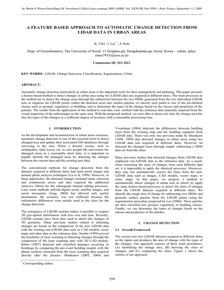
In: Bretar F, Pierrot-Deseilligny M, Vosselman G (Eds) Laser scanning 2009, IAPRS, Vol. XXXVIII, Part 3/W8 – Paris, France, September 1-2, 2009 Contents Keyword index Author index A FEATURE BASED APPROACH TO AUTOMATIC CHANGE DETECTION FROM LIDAR DATA IN URBAN AREAS K. Choi , I. Lee * , S. Kim Dept. of Geoinfomatics, The University of Seoul, 13 Siripdea-gil, Dongdeamun-gu, Seoul, Korea – (shale, iplee, sinus7953)@uos.ac.kr Commission III, WG III/2 KEY WORDS: LIDAR, Change Detection, Classification, Segmentation, Urban ABSTRACT: Automatic change detection particularly in urban areas is the important tools for their management and planning. This paper presents a feature based method to detect changes in urban area using two LIDAR data sets acquired at different times. The main processes in the method are to detect the change areas through the subtraction between the two DSMs generated from the two individual LIDAR sets, to organize the LIDAR points within the detected areas into surface patches, to classify each patch to one of the pre-defined classes such as ground, vegetation, or building, and to determine the types of the change based on the classes and properties of the patches. The results from the application of the method to real data were verified with the reference data manually acquired from the visual inspection of the orthoimages in the same area. With the proposed method, we were able to detect not only the change area but also the types of the changes in a sufficient degree of accuracy with a reasonable processing time. Vosselman (2004) detected the differences between building layer from the existing map and the building segments from LIDAR data. There was only one previous study by Murakami (1998, 1999) that detected changes in urban areas using two LIDAR data sets acquired at different dates. However, he detected the changed areas through simply subtracting a DSM data set from the other. 1. INTRODUCTION As the development and reconstruction of urban areas increases, automatic change detection is one of the essential tools to detect changed area and update their associated GIS databases through surveying in the area. When a disaster occurs, such as earthquakes, tidal waves, etc, to save people life and restore the damaged areas in a reasonably short time, it is important to rapidly identify the damaged areas by detecting the changes between the current data and the existing past data. Many previous studies that detected changes from LIDAR data employed non-LIDAR data as the reference data. As a result, when extracting the clues of changes from each different data set, it is impossible to apply the identical processes. Moreover, they may not automatically extract the clues from the nonLIDAR data such as images, CAD models, vector maps, or raster maps. In this paper, we propose a method to automatically detect changes in urban area in which we apply the same feature-based processes to detect the clues of changes from the LIDAR datasets acquired at different dates. We identify the rough area of change by subtracting two DSMs and generate surface patches from the LIDAR points using the segmentation procedure proposed by Lee (2006). These patches are then classified into ground, vegetation, or building classes. Finally, we can determine the types of changes based on the classes and properties of the patches. The conventional methods for change detection from the datasets acquired at different dates had used aerial images and manual photo analysis techniques (Lu et al, 1998). However, in these approaches, the detected changes included many omission and commission errors and thus required the additional intensive efforts for the subsequent manual editing processes. Later some methods utilized digital aerial, satellite images, and aerial stereopairs (Jung, 2004) but allowed only partial automation; the accuracy was not sufficient because the radiometric differences were mainly used as the clues for the change detection. The emergence of LIDAR systems makes it possible to acquire 3D geo-spatial information with less cost and time. Recently, LIDAR systems have been thus used to detect the changes of 3D geometry. Many previous studies related to detecting changes are based on the comparison of the new LIDAR data with the existing non-LIDAR data such as CAD models, raster maps and other data as the reference data. Steinle (1999) proved the feasibility of laser scanning in detecting changes through the comparison of the laser scanning data with 3D CAD models. Rehor (2007) detected and classified damages occurring in buildings by comparing the pre-event building models with the planar surfaces extracted from the laser scanning data acquired directly after the disaster. Matikanen (2003, 2004) and * 2. CHANGE DETECTION 2.1 Overall Framework The system uses two LIDAR datasets acquired at different dates as the inputs and produces the area of change with the types of the changes. Our approach consists of three main procedures: (A) identifying the change area, (B) deriving the clues of changes, and (C) comparing the clues. Figure 1 shows the outline of our approach. Corresponding author. 259 In: Bretar F, Pierrot-Deseilligny M, Vosselman G (Eds) Laser scanning 2009, IAPRS, Vol. XXXVIII, Part 3/W8 – Paris, France, September 1-2, 2009 Contents Keyword index Author index INPUT LiDAR Data1 LiDAR Data2 DSM 1 DSM 2 Step (A) Extracting Aera of Change Difference Image Data 1 in the area of change Data 2 in the area of change Planar Patches 1 Planar Patches 2 Class and Properties of Patches 1 Class and Properties of Patches 2 Step (B) Creating Clues of Change Step (C) Comparing Clues of Change OUTPUT Figure 4. Difference image. The difference image which stores the variation of height between two occasions is converted to binary images as Figure 5 to extract the MBRs of the changed areas. The binary image often contains commission errors, due to the horizontal error of the LIDAR system and occlusions, that cause them to be recognized as changed along the boundary of unchanged buildings. We applied the opening operator to the binary image to minimize these effects. It is able to open the gaps between the objects and eliminate fine hairs and small protrusions through performing dilation following erosion (Davies, 2005). Figure 6 shows the result of this opening operation. Change of Class and Properties Class of detected changes Figure 1. Outline of the proposed method. 2.2 Identifying Changed Areas We can recognize some simple changes from height differences between two input LIDAR data. Initially, we generate DSMs with the interval of 1m and subtract one from the other to extract the rough horizontal boundaries of the changed areas. Figure 2 and 3 are the DSMs generated from each LIDAR data set. Figure 4 shows the difference image generated through subtracting one (2007) from the other (2005). Figure 5. Binary image. Figure 2. DSM (2005). Figure 6. Opened binary image. A special filter is designed and then applied to remove those commission errors which may exist after opening. The filter converts all black cells within the template to white if the number of white cells in the template area is greater than a threshold. The threshold is set to 90% and the result is presented in Figure 7. We then group the white cells, in which their heights are changed, based on connectivity, as shown in Figure 8. Next, the MBRs of the objects are extracted after each group of the cells as one object. The number of extracted MBRs is 11. Figure 3. DSM (2007). 260 In: Bretar F, Pierrot-Deseilligny M, Vosselman G (Eds) Laser scanning 2009, IAPRS, Vol. XXXVIII, Part 3/W8 – Paris, France, September 1-2, 2009 Contents Keyword index Author index INPUT : LIDAR Data (ID : 10) 2005 2007 Figure 7. Filtering results. OUTPUT : Planar Patches (ID : 10) 2005 Figure 8. Grouping results. 2.3 Creating clues of changes 2007 Figure 9. Patches generated from the segmentation process. The clues of changes are generated from the LIDAR data within the extracted MBRs. We use the classes and properties of planar surface patches organized through the segmentation of the LIDAR data. 2.3.1 Segmentation: We adapt the segmentation method proposed by Lee (2000). The method works by generating surface patches from seed patches based on region growing methodology. The main processes are as follow. First, we establish the adjacency among the points which are in the range of 2.5m. Then we generate seed patch candidates based on 10 points which are distributed close to each other. We grow surface patches by iteratively adding the adjacent points to those after computing parameters of the seed patches. For the growing process, we perform the F-test where random variable is the ratio of dispersions of the current patch and that of the newly applied points and the significance level is set to 0.05. The surface patches that have completed their growing are defined as the parameters of the approximated plane, the roughness of the plane, the points within the patch and their boundary. Figure 9 shows the segmentation results in Area 10 among the identified 11 changed areas. We can obviously recognize remarkable contrast in the detected area by comparing the shape, size, and location of patches in 2005 and 2007. 2.3.2 Classification of Patches: Segmented patches are classified into either ground, vegetation, or building classes by considering the use of land in urban area. Figure 10 illustrates the procedure of this classification. Patches to be classified into the ground class are the cluster with the largest area and lowest height. Therefore, we rank the clusters in the order of their size of the area and lowness and, then, classify the patches of the cluster with the minimum sum of two ranks into the ground class. The patches which are excluded from the ground class are classified into either vegetation or building classes. It is not likely for vegetation to have even plane, large area and high height in comparison with buildings in urban area. Therefore, the patches with high roughness (defined as the standard deviation resulted from fitting a patch to the points), small area and low height are classified into vegetation class while the remaining clusters are assigned into building class. C1, C1,C2, C2,C3 C3 YES Ground GroundCluster? Cluster? NO Patches are grouping into meaningful surface clusters based on the connectedness and elevatedness calculated between the patches so that the patches in a same cluster may originate from the same object. The connectedness is the proportion of the distance between the edges of one and the other, the length of edges and points density of each patch by considering all edges in two patches. The elevatedness is a proportion of the difference between the height and length of edges of two adjacent patches in 2D. C1 C1 C2, C2,C3 C3 Roughness Roughness>>threshold, threshold, Size, Size,Height Height<<threshold threshold C 1 : ground C 2 : vegetation C2 C2 C3 C3 Figure 10. Classification process. 261 C 3 : building In: Bretar F, Pierrot-Deseilligny M, Vosselman G (Eds) Laser scanning 2009, IAPRS, Vol. XXXVIII, Part 3/W8 – Paris, France, September 1-2, 2009 Contents Keyword index Author index The proper thresholds of roughness, size and height are set up for patch classification. In our pre-experiments, we classified the patches into either vegetation or building classes through comparing with the naked eye segmented patches and aerial images in the same area. We measured the roughness, size, and height of vegetation and building patches then found suitable thresholds to distinguish between the two classes. Table 1 shows these derived thresholds. Properties Thresholds Roughness 0.35 Size 100 (m2) Height 10 (m) 2.4 Comparing Clues of Changes We cannot guarantee that patches equally are organized from two datasets in unchanged area. Therefore, we compare the properties and classes of patches in a grid basis. The area of a patch is at least larger than 5 m2 from the consideration that the point density of LIDAR data used for this study is about 2.6 points/m2 and a seed patch starting to grow includes 10 LIDAR points. Therefore, the size of cell, 1m by 1m, is sufficient to detect changes in urban area. All the cells of the class maps are assigned with the values of the class type and the properties of patches such as roughness, normal vector, height, etc. The changes are detected by comparing the class maps. The classes of patches are more meaningful than the properties of patches because they are determined using the properties of patches. Therefore, at first, the classes of patches are compared as shown in Figure 12. All the changes are detected by comparing the classes of patches. However, in reality the change may happen without the changes in classes of patches. For example, when new higher buildings are built in the area where lower buildings existed. Therefore, we compare the properties of patches to identify the cases when the changes happen without the changes in classes of patches. The properties of patches to be compared include height, roughness and normal vector. If the properties of patches were not changed, it would be likely to have no change. On the other hands, if the properties of patches were changed, it would be likely to have some change. The change in height is identified as being higher or lower in the building class. In case that roughness and normal vector are changed without the variation in height, it should remain as indefinable. Table 3 shows 10 categories of the detected changes. Table 1. Classification thresholds. We generate grid layers with the same size of change areas which have intervals of 1m in x and y directions. Each cell is assigned the patch’s class by matching with the patch including horizontal position of the cell. The cells that have not been assigned a patch’s class, are classified as “no data”. Figure 11 is the class map of area with ID 10. Black points, mean “no data”, are found a large number at the boundaries of buildings or turning points of roofs. This is because these locations have high possibility to be the occlusion areas and also they does not include seed patch to grow to surface patch due to their small area. INPUT : Planar Patches (ID : 10) 2005 2007 OUTPUT : Class Maps (ID : 10) Figure 12. Classification of changes 2005 2007 Figure 11. Classification of patches 262 In: Bretar F, Pierrot-Deseilligny M, Vosselman G (Eds) Laser scanning 2009, IAPRS, Vol. XXXVIII, Part 3/W8 – Paris, France, September 1-2, 2009 Contents Keyword index Author index code categories R1 ground → vegetation R2 ground → building R3 vegetation → ground R4 vegetation → building R5 building → ground R6 building → vegetation R7 increase of height in building R8 decrease of height in building R9 no change R10 Undefinable change Table 2. Categories of changes Figure 13 shows the change map of Area 10. The pink points in the central part of the map mean the change from ground to building. The blue crosses in the lower part of the map indicate increase in the height of buildings. This actually means that there is new higher building at the position of old lower building. The green crosses on the higher part of the map indicate that vegetation grows on the ground. We then can recognize that there have been some constructions of new building on the center and also some reconstruction at the lower part of the area. Figure 14. LIDAR data in the identified change areas and the generated change maps. 4. VERIFICATION Since the change detection is performed through the classification of surface patches, the verification of the patch classification is important. For this reason, we verify the correctness of the patch classification by overlaying the class map on top of the orthoimages at the same area. Figure 15 shows the class maps of Area 10 and 11 over the orthoimages. Almost every cell of the ground and building classes is correctly allocated. The green points indicating the vegetation class are clearly shown on the vegetation areas of the orthoimages. Figure 13. Change map ID : 10 3. EXPERIMENTAL RESULTS We have applied the proposed method to detect the changes in the data acquired from a urban area of Ilsan, Korea in 2005 and 2007. From the experiments, 11 changed areas were identified. 7 areas among these areas were under construction. We excluded the construction sites because they are difficult to explain with the pre-defined classes. Figure 14 presents the generated change maps. 2005 2007 ID : 11 2005 2007 Figure 15. Class maps over the orthoimages 263 In: Bretar F, Pierrot-Deseilligny M, Vosselman G (Eds) Laser scanning 2009, IAPRS, Vol. XXXVIII, Part 3/W8 – Paris, France, September 1-2, 2009 Contents Keyword index Author index The verification of the detected changes can also be performed by comparing the change maps with the two orthoimages. Figure 16 is the change maps of Area 10 and 11. The pink points within Area 10 indicate a new building built-up. The correctness can be confirmed from that the building does not exist in the orthoimage of 2005 but in 2007. The blue crosses and circles in the center of Area 11 show the vertical changes of buildings. Therefore, we can notice that a building existed in 2005 was reconstructed in 2007. Lee, I., 2006. Segmentation of Airborne LIDAR Data: From Points to Patches, Korean Journal of Geomatics, KSGPC, Vol. 24, No. 1, pp. 1-11. Lee, I., 2006. A Feature Based Approach to Extracting Ground Points from LIDAR Data, Korean Journal of Remote Sensing, The Korean Society of Remote Sensing, Vol.22, No.4, pp.265274. Lee, I., 2004. An Efficient and Robust Approach to Digital Elevation Model(DEM) Generation from Airborne Laser Scanner(ALS) Data, Civil Engineering Conference in the Asian Region (CECAR), Seoul, Korea. (A) ID : 10 Moon, J., 2005. Surface Segmentation using LiDAR data and Digital Image, master dissertation, University of Seoul, Seoul, Korea. 2005 2007 Park, J., 2005. Automatic Building reconstruction from LIDAR data and a digital map, master dissertation, University of Seoul, Seoul, Korea. (B) ID : 11 Kuo-Hsin, H., 2006. Terrain Change Detection Combined Photogrammetric DEM and Airborne LIDAR data, ACRS2006, Ulaanbaatar, Mongolia 2005 2007 Matikainen, L., 2004. Automatic Detection of Changes from Laser Scanner and Aerial Image data for Updating Building Maps, XXth ISPRS Congress, Istanbul, Turkey Figure 16. Comparison of the change maps and orthoimages Matikainen, L., 2003. Automatic Detection of Changes from Laser Scanner data for Map Updating, ISPRS Symposium Commission3 WG3, Vol. 34, part3. 5. CONCLUSION In this paper, we proposed a feature-based method to rapidly detect changes in the urban area using LIDAR data. The main processes of the proposed method are detecting change areas through the subtraction of two DSMs generated from the LIDAR sets, (2) organizing the LIDAR points within the detected areas into surface patches, (3) classify each patch to a pre-defined class such as ground, vegetation, and building, and (4) determining the types of changes based on the class and properties of the patches. Murakami, H., 1999. Change Detection of Buildings Using an Airborne Laser Scanner, ISPRS Journal of Photogrammetry & Remote Sensing, Vol. 54, pp.148-152. Murakami, H., 1998, Potential of an Airborne Laser Scanner System for Change Detection of Urban Features and Orthoimage Development, IAPRS , Vol. 32, part4. p.422-427. Rehor, M., 2007. Classification of Building Damages based on Laser Scanning data, proccedings of ISPRS workshop, ISPRS, Vol. 36, part 3, pp.67-72. The experimental results of the application of the proposed method to real data were verified with the orthoimages generated from aerial images simultaneously acquired with LIDAR data. With the proposed method, we were able to detect not only the change area but also the types of the changes in a sufficient degree of accuracy with a reasonable processing time. However, there is no quantitative evaluation. In the future, we will establish the quality criteria to evaluate the performance of our method. Steinle, E., 1999. Assessment of Laser Scanning Technology for Change Detection in Buildings, proceedings CIPA International Symposium, Olinda, Brazil. Vol. 17. Thuy Vu, T., 2004. LIDAR-based Change Detection of Buildings in Dense Urban Areas, Geoscience and Remote Sensing Symposium, 2004 IGARSS, Vol. 5, pp.3413-3416. REFERENCES Davies, E.R., 2005. Machine Vision, Elsevier, San Francisco, pp.232-281. Vosselman, G., 2004. Change Detection for Updating Mediun Scale Maps Using Laser Altimetry, International Archives of Photogrammetry, Remote Sensing and Spatial Information Sciences, Vol. 34, part B3, pp. 207-212. Forlani, G., 2006. Complete Classification of Raw LIDAR data and 3D Reconstruction of Buildings, Pattern Analysis & Applications, Springer London, Vol. 8, No. 4, pp.357-374. ACKNOWLEDGEMENTS Jung, F., 2004. Detecting building changes from multitemporal aerial stereopairs, ISPRS Journal of Photogrammetry & Remote Sensing, Vol. 58, pp.187-201. This research was supported by a grant (07KLSGC03) from Cutting-edge Urban Development - Korean Land Spatialization Research Project funded by Ministry of Land, Transport and Maritime Affairs. 264
