DETECTING AND TRACKING VEHICLES IN A ROUNDABOUT
advertisement

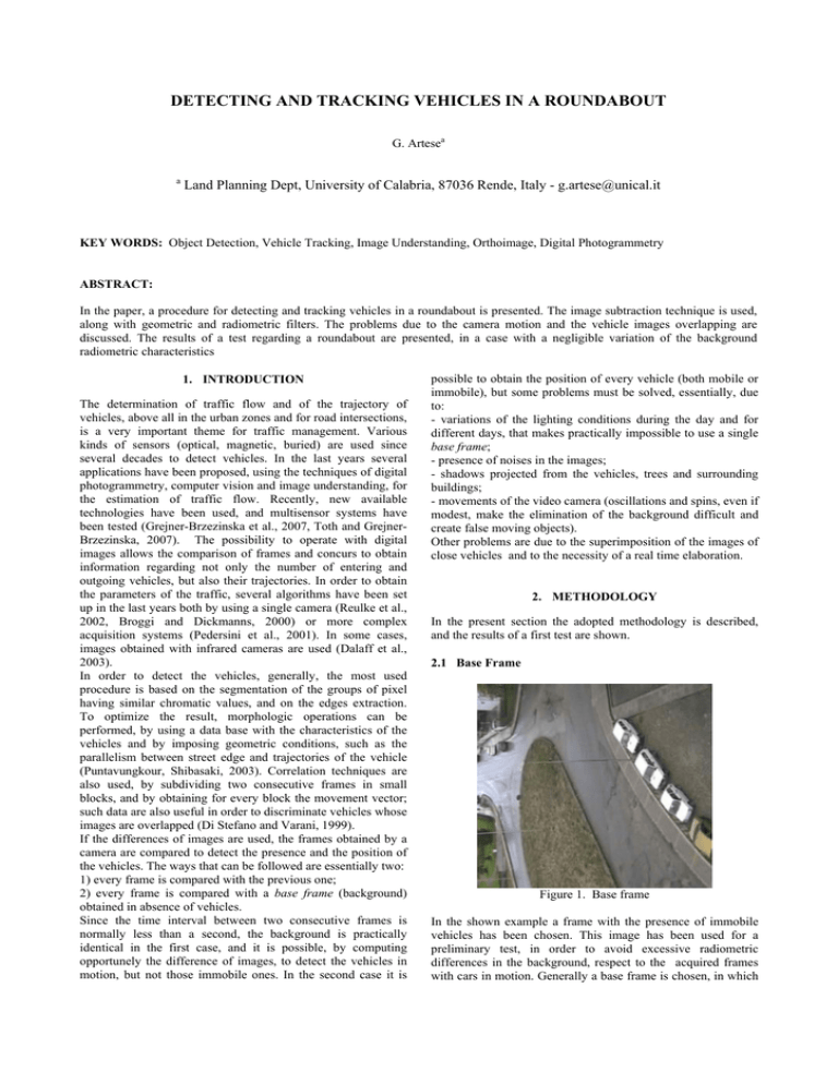
DETECTING AND TRACKING VEHICLES IN A ROUNDABOUT G. Artesea a Land Planning Dept, University of Calabria, 87036 Rende, Italy - g.artese@unical.it KEY WORDS: Object Detection, Vehicle Tracking, Image Understanding, Orthoimage, Digital Photogrammetry ABSTRACT: In the paper, a procedure for detecting and tracking vehicles in a roundabout is presented. The image subtraction technique is used, along with geometric and radiometric filters. The problems due to the camera motion and the vehicle images overlapping are discussed. The results of a test regarding a roundabout are presented, in a case with a negligible variation of the background radiometric characteristics 1. INTRODUCTION The determination of traffic flow and of the trajectory of vehicles, above all in the urban zones and for road intersections, is a very important theme for traffic management. Various kinds of sensors (optical, magnetic, buried) are used since several decades to detect vehicles. In the last years several applications have been proposed, using the techniques of digital photogrammetry, computer vision and image understanding, for the estimation of traffic flow. Recently, new available technologies have been used, and multisensor systems have been tested (Grejner-Brzezinska et al., 2007, Toth and GrejnerBrzezinska, 2007). The possibility to operate with digital images allows the comparison of frames and concurs to obtain information regarding not only the number of entering and outgoing vehicles, but also their trajectories. In order to obtain the parameters of the traffic, several algorithms have been set up in the last years both by using a single camera (Reulke et al., 2002, Broggi and Dickmanns, 2000) or more complex acquisition systems (Pedersini et al., 2001). In some cases, images obtained with infrared cameras are used (Dalaff et al., 2003). In order to detect the vehicles, generally, the most used procedure is based on the segmentation of the groups of pixel having similar chromatic values, and on the edges extraction. To optimize the result, morphologic operations can be performed, by using a data base with the characteristics of the vehicles and by imposing geometric conditions, such as the parallelism between street edge and trajectories of the vehicle (Puntavungkour, Shibasaki, 2003). Correlation techniques are also used, by subdividing two consecutive frames in small blocks, and by obtaining for every block the movement vector; such data are also useful in order to discriminate vehicles whose images are overlapped (Di Stefano and Varani, 1999). If the differences of images are used, the frames obtained by a camera are compared to detect the presence and the position of the vehicles. The ways that can be followed are essentially two: 1) every frame is compared with the previous one; 2) every frame is compared with a base frame (background) obtained in absence of vehicles. Since the time interval between two consecutive frames is normally less than a second, the background is practically identical in the first case, and it is possible, by computing opportunely the difference of images, to detect the vehicles in motion, but not those immobile ones. In the second case it is possible to obtain the position of every vehicle (both mobile or immobile), but some problems must be solved, essentially, due to: - variations of the lighting conditions during the day and for different days, that makes practically impossible to use a single base frame; - presence of noises in the images; - shadows projected from the vehicles, trees and surrounding buildings; - movements of the video camera (oscillations and spins, even if modest, make the elimination of the background difficult and create false moving objects). Other problems are due to the superimposition of the images of close vehicles and to the necessity of a real time elaboration. 2. METHODOLOGY In the present section the adopted methodology is described, and the results of a first test are shown. 2.1 Base Frame Figure 1. Base frame In the shown example a frame with the presence of immobile vehicles has been chosen. This image has been used for a preliminary test, in order to avoid excessive radiometric differences in the background, respect to the acquired frames with cars in motion. Generally a base frame is chosen, in which no vehicles are present. In such a way it will be possible to identify also the vehicles in pause. The base frame will be replaced from the last frame in which no vehicles are present. 2.2 Image subtraction, object detection and labelling Figure 5. Edges dilatation Figure 2. Compared frame Figure 6. Region filling Figure 3. Frames difference In the first tests, the RGB images have been transformed to greyscale. For every frame (Figure 2), the subtraction of the base image is performed. A new image is obtained, in which the pixel with no radiometric differences are black, and those for which variations have been detected have non zero values (Figure 3). Figure 7. Regions erosion Figure 4. Edges Extraction These pixel are grouped through a segmentation operation and some areas are detected, whose edges are extracted with classic techniques (Canny, 1986) (Figure 4). An expansion of the edges is then performed, in order to connect possible open lines (Figure 5). To this point, the regions surrounded by closed lines are filled (Figure 6). In order to bring back to the original dimensions the filled regions, an erosion of the edges is performed (Figure 7). A filter is used to eliminate the regions with a width less than a selected threshold; every obtained area, corresponding to a vehicle, is labelled (Figure 8). The image of Figure 2 has been acquired from a slightly different position respect to the base image, in order to simulate a possible movement of the camera. In an operating situation, to Figure 8. Regions labelling have the view of a whole roundabout, the camera should be positioned in a high position (fixed to a pole or to a zeppelin), so oscillations are expectable. Because of the movement of the camera, the confronted frames are roughly aligned, so numerous “false” areas will be detected. In order to eliminate such areas, the images are rectified by using automatically detectable targets, positioned on known points external to the road area. In such a way all frames can be considered to be referenced. Several kinds of targets are used in close range photogrammetry (Fraser, 1997); for specific aims, peculiar design are adopted (Artese, 2006). In our example the images have been aligned by using common features. Figure 9 shows the result of the subtraction between the aligned frame of Figure 2 and the base frame; the extracted edges are shown in Figure 10. In Figure 11 the superimposition of the detected areas on the original frame can be observed, while in Figure 12 the labelled regions are represented. It can be observed that, in this case, only three areas have been labelled, corresponding to the moving vehicles. Figure 9. Aligned frame difference Figure 11. Edges superimposition Figure 12. Regions labelling 2.3 Vehicle recognition and tracking We must now recognize the entering vehicles and those already present in the previous frames, to determine their trajectories. To such scope the following procedure has been adopted, for every couple of consecutive frames: - in the first frame the coordinates of the moving vehicles are known; this vehicles have been opportunely labelled; - for every region detected in the second frame, the coordinates of the barycentre (in pixel) are found; - every vehicle of the first frame is confronted with every region of the second frame and there are obtained the distance, the march direction (clockwise or counter-clockwise) and the ratio between the areas; a table is obtained in which, for every vehicle, the regions of the second frame compatible for trajectory and dimension are obtained. In this case, the radiometric characteristics have been not used. – by using the table, the number of the corresponding vehicle is assigned to every region; in case of incoming vehicles, the number of the last vehicle increased by one will be assigned. 3. THE TEST Figure 10. Edge extraction In order to estimate the feasibility of the described procedure, a test has been executed on a portion of roundabout in the city of Cosenza. It has be used a digital camera “Sony Handycam TRV14E”; its software allowed the extraction of the frames, with an interval of a second. For the elaboration of the images and the comparisons the MatlabTM software has been used, while the tables have been built by means of an electronic sheet. Five consecutive frames are shown in the following, with overlapped the detected regions and the figures obtained with the automatic labelling. The comparison between frames Figure 13. Frame 54300 with edges and labelling 54300, (in which the two vehicles are labelled with numbers 55 and 56) and 54400 (in which the regions are labelled with numbers 1, 2, 3), can be easily obtained by confronting the rotation direction. In Table 1 the values of the areas and the coordinates (line, column) in pixel of the centroids of the vehicles of frame 54300 and of the regions of frame 54400 are reported. It is also reported the value of the rotation angle respect to a half-line outgoing from the centre of the roundabout (polar coordinate). The sign of the rotation angle increment helps us to determine the possible correspondence between a vehicle of the previous frame and a region of the present one. In our case it can be easily observed that vehicle 55 is only compatible with region 1 of frame 54400 and that vehicle 56 is compatible, consequently, only with region 2. Region 3, therefore, will represent a vehicle entering the considered roundabout zone. In Table 2 the increments of the rotation angle and a value of compatibility (Y, N) between vehicles and regions are shown, while in table 3 the labelling of the regions of frame 54400 are reported, along with the average speed of the vehicles, in the period of time between the acquisitions of frame 54300 and 54400. The described operation can be repeated with frame 54500. One obtains one outgoing vehicle and an entering one (n. 58). Frame 54600 generates four regions, one of which will be eliminated by imposing the minimum value to the areas, and the procedure can be repeated with good results. In frame 54700, after the elimination of the two very small areas, four regions are labelled, while in the original image with the overlapped edges, the presence of only three vehicles is evident. In Table 4 the values of the areas and the coordinates of the barycentres of the vehicles of frame 54600 and of the regions of frame 54700 are reported, along with the value of the rotation angle. Figure 14. Frame 5440 with edges and labelling Frame 54300 Frame 54400 Label 55 56 1 2 3 area 835 1835 586 1430 472 Barycentre Row 122.96 173.6 53.7 129.4 237.52 Barycentre Column 147.77 176.98 130.29 150.33 169.67 teta 2.684 2.113 2.961 2.634 1.324 Table 1. Areas, Barycentre coordinates, rotation angles for vehicles and regions 1 ∆ϑ 55 0.277 2 3 Compat. ∆ϑ Compat. ∆ϑ Compat. Y -0.049 N -1.359 N 56 0.848 Y 0.521 -0.788 N Y Table 2. Rotation increments and compatibility between vehicles and regions Labelling for the frame 54400 Region Label 1 2 3 Vehicle Label 55 56 57 Velocity (pixel/sec) 71.4 51.6 Incoming Table 3. Region Labelling and Velocities Figure 15. Frame 54500 with edges and labelling Figure 17. Frame 54700 with edges and labelling Label area Frame 54600 56 57 58 568 768 1358 2 586 Frame 54700 3 4 5 595 420 642 Barycentre row 60.61 127.7 196.32 63.29 88.76 111.09 104.12 Barycentre column 93.84 130.42 166.39 69.03 112.37 135.53 151.12 teta 3.180 2.823 1.913 3.336 3.047 2.826 2.726 Table 4. Areas, Barycentre coordinates, rotation angles for vehicles and regions Frame 54700 2 3 4 5 % Y/ % Y/ % Y/ % Y/ ∆ϑ area N ∆ϑ area N ∆ϑ area N ∆ϑ area N 56 0.156 103 Y -0.13 105 N -0.35 73.9 N -0.45 113 N 57 0.513 76.3 0.224 77.5 Y 0.003 54.7 N -0.09 83.6 N 58 1.423 43.2 N 1.134 43.8 N 0.912 30.9 N 0.812 47.3 N Table 5. Rotation increments, Area ratio and Compatibility (Y/N) between vehicles and regions Figure 16. Frame 54600 with edges and labelling Table 5 shows the rotation angles and the areas of the vehicles detected in frame 54600 with numbers 56, 57 and 58, along with rotation angles and areas of the regions selected in the frame 54700 after the exclusion of small areas (regions 2, 3, 4 and 5). A comparison is carried out by using the difference of the angles and the ratio of the areas of the regions identified in frame 54700 with those identified in frame 54600. From the aforesaid table of comparison, the compatibility between the areas identified in the two frames can be obtained. The area 56 is compatible only with region 2 (for regions 3, 4 and 5 the difference of rotation angles is negative and indicates an opposite direction of the vehicle); area 57 is compatible only with region 3 (in this case the angle difference with region 4 is nearly null even if positive, but the ratio between the areas is incompatible, also considering the scale difference in different portions of the image). The position of vehicle 58 is compatible with regions 4 and 5, but the ratio between the areas of regions 4 and 5 and that one of vehicle 58 is too small. However, in the frame 54700 there is one more identified vehicle respect to frame 54600: that could presuppose a new entering vehicle, but it would be too much advanced if we consider the time elapsing between two consecutive frames. For this reason a comparison between the area of the vehicle 58 and the sum of the areas of regions 4 and 5 is performed, assuming that the area of vehicle 58 has been segmented in two close regions. The sum of the areas of regions 4 and 5 corresponds to approximately 78% of the area of vehicle 58. This ratio is compatible, taking into account the scale factor in the selected zone of the image. The barycentres of regions 4 and 5 are, moreover, very close. In table 6 the labelling of the regions of frame the 54700, and the average speeds of the vehicles are reported. Labelling for the frame 54700 Region Label 2 3 4 + 5 Vehicle Label 56 57 58 Velocity (pixel/sec) 25.0 42.9 91.7 Table 6. Region Labelling and Velocities 4. WORK IN PROGRESS The present work regards edge matching applications and neural networks. Edge matching is a technique used for target recognition (Olson, C.F., Huttenlocher, D.P., 1997). The edges extracted in a frame can be used for the detection of the vehicles in the next frame. It is possible to observe that the contour of a vehicle doesn’t have big changes from a frame to the next one. Some problems due to the separation of a single vehicle, discussed for frame 54700, can be overcome using the matching of the silhouettes. In our case a rotation should be applied to the selected silhouette, take into account the velocity and the radius of the roundabout. A back propagation neural network has been studied, with three layers. In order to reduce the computing time, a pre-processing stage is foreseen to reduce the size and dimensionality of the input pattern (Ahmed et al., 2005). The implementation of the network will be realized using MatlabTM software. 5. CONCLUSIONS AND FUTURE DEVELOPMENTS A methodology has been described, for the vehicles detection in a roundabout and for the determination of their trajectories. The results of a test lead on a real case have been described. Next studies will be addressed to the resolution of the problems to face, with particular regard to the radiometric variations of the background image, to the superimposition of the vehicles and the elimination of the shadows from the regions associated to the vehicles. It will be used, moreover, the radiometric average value of the extracted regions. REFERENCES Ahmed, J., Jafri, M. N., Ahmad, J., Khan, M.I., 2005. Design and Implementation of a Neural Network for Real-Time Object Tracking . In: Transaction on Engineering, Computing and Technology, Vol. 6, pp.209-212. Artese, G., 2007. ORTHOROAD: A low cost mobile mapping system for road mapping. In: Advances in Mobile Mapping Technology, Tao C.Vincent and Li J. editors, Taylor & Francis, London, pp. 31-42. Broggi, A. and Dickmanns, E. D., 2000. Applications of computer vision to intelligent vehicles. In: Image and Vision Computing, 18(5): pp. 365–366. Canny, J., 1986. A computational approach to edge detection. PAMI, 8:679–698. Dalaff, C., Reulke,n R., Kroen, A., Kahl, T., Ruhe, M., Schischmanow, A., Schlotzhauer, G., Tuchscheerer, W., 2003. A Traffic Object Detection System for Road Traffic Measurement and Management. http://www.sprg. massey.ac.nz/ivcnz/Proceedings/IVCNZ_15.pdf , (accessed 25 May 2006) Di Stefano, L., Varani, E., 1999. Vehicle Detection and Tracking Using the Block Matching Algorithm. http://www.vis.dm.unibo.it/~eviarani/research/publications /imacs99/imacs99.pdf (accessed 25 May 2006) Fraser, C.S., 1997. Innovations in Automation for Vision Metrology Systems. In: Photogrammetric Records, 15(90), pp. 901-911 Grejner-Brzezinska, D.A., Toth, C.K. and Paska, E., 2007. Airborne remote sensing supporting traffic flow estimation. In: Advances in Mobile Mapping Technology, Vincent Tao C. and Li J. editors, Taylor & Francis, London, pp. 51-60. Olson, C.F., Huttenlocher, D.P., 1997. Automatic target recognition by matching oriented edge pixels. In: IEEE Transactions on Image Processing, vol. 6, n. 1, pp.103-113 Pedersini, F., Sarti, A. and Tubaro, S., 2001. Multi-camera parameter tracking. In: IEE Proceedings -Vision,Image and Signal Processing, 148(1): pp. 70– 77. Puntavungkour, S., Shibasaki, R., 2003. Novel Algorithm of Vehicle Detection by Using New Ultra Resolution Aerial Image, Three Line Scanner. In: Reports IEEE_CSMC .http://www.shiba.iis.u-tokyo.ac.jp/publications/ thesis/2003 /Sompochpaper/Sompoch_paper7.pdf, ,(accessed 25 May 2006) Reulke, R., Boerner, A., Hetzheim, H., Schischmanow A. and Venus, H., 2002, A sensor web for road-traffic observation. In Image and Vision Computing - New Zealand, pp. 293–298. Toth, C.K., Grejner-Brzezinska, D.A., 2007. Vehicle classification from LIDAR data to support traffic flow estimates. In: Advances in Mobile Mapping Technology, Vincent Tao C. and Li J. editors, Taylor & Francis, London, pp. 119-130.


