A NEW METHOD DERIVED FROM TIME-VECTOR ANALYSIS FOR GENERATION
advertisement

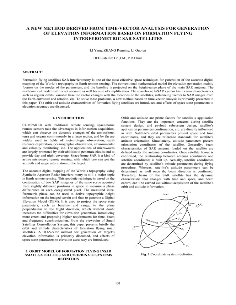
A NEW METHOD DERIVED FROM TIME-VECTOR ANALYSIS FOR GENERATION OF ELEVATION INFORMATION BASED ON FORMATION FLYING INTERFEROMETRIC SAR SATELLITES LI Yang, ZHANG Running, LI Guojun DFH Satellite Co.,Ltd., P.R.China ABSTRACT: Formation flying satellites SAR interferometry is one of the most effective space techniques for generation of the accurate digital mapping of the World’s topography in Earth remote sensing. The conventional mathematical model for elevation generation mainly focuses on the modes of the parameters, and the baseline is projected on the height-range plane of the main SAR antenna. The mathematical model itself is not accurate as well because of simplification. The spaceborne InSAR system has its own characteristics, such as regular orbits, variable baseline vector changes with the locations of the satellites, influencing factors to SAR images from the Earth curvature and rotation, etc. To solve these problems, a new method based on time-vector analysis is primarily presented in this paper. The orbit and attitude characteristics of formation flying satellites are introduced and effects of space state parameters to elevation accuracy are discussed. Orbit and attitude are prime factors for satellite’s application functions. They are the important contents during satellite system design, and payload subsystem design, satellite’s application parameters confirmation, etc. are directly influenced as well. Satellite’s orbit parameters present space and time coordinates, and they are reference standards for satellite’s attitude orientation. Simultaneity, attitude parameters present orientation coordinates of the satellite. Generally, beam characteristics of SAR antenna loaded on the satellite are defined under the antenna coordinates. Once satellite layout is confirmed, the relationship between antenna coordinates and satellite coordinates is built up. Actually, satellite coordinates are determined by satellite’s attitude parameters during flying procedure. Whereas, satellite’s attitude parameters can be determined as well once the beam direction is confirmed. Therefore, beam of the SAR satellite has the dynamic characteristic that changes with time and space, and beam control can’t be carried out without acquisition of the satellite’s orbit and attitude information. x p xa ze z 1. INTRODUCTION COMPARED with traditional remote sensing, space-borne remote sensors take the advantages in infor-mation acquisition, which can observe the dynamic changes of the atmosphere, terra and oceans conti-nuously in a large region, and by far are widely used in fields of meteorologic observation, earth resource exploration, oceanographic observation, environmental and calamity monitoring, etc. The applications of microwaves are largely promoted by their abilities to penetrate clouds and to provide day and night coverage. Space-borne SAR is a kind of active microwave remote sensing, with which one can get the azimuth and range information of the target. The accurate digital mapping of the World’s topography using Synthetic Aperture Radar interfero-metry is still a major topic in Earth remote sensing. This geodetic technique is based on the combination of two SAR imagines of the same scene acquired from slightly different positions in space to measure a phase differ-rence in each coregistered pixel. The measured interferometric phase can be used to derive topographic height information on the imaged terrain and thus to generate a Digital Elevation Model (DEM). It is used to project the space state parameters, such as baseline and range, to the plane perpendicular to the flight direction, which without doubt increases the difficulties for eleva-tion generation, introducing more errors and proposing higher requirements for time, beam and frequency synchronization. From the viewpoint of Small Satellites Constellation System, this paper presents briefly the orbit and attitude characteristics of formation flying small satellites. A 3D-Vector method for generation of target’s elevation information is primarily discussed, and effects of space state parameters to elevation accu-racy are introduced. xo S y p ya z p za Gree nwic h xe y zo x 2. ORBIT MODEL OF FORMATION FLYING INSAR SMALL SATELLITES AND COORDINATE SYSTEMS DEFINITION yo o ye Fig. 1 Coordinate systems definition 131 The International Archives of the Photogrammetry, Remote Sensing and Spatial Information Sciences. Vol. XXXVII. Part B3b. Beijing 2008 xa " ya ' S1 N S1 z ' θ1 a A x ' xa a ψ1 za " T T vˆs11 o o ε1 θ1 ψ1 o S1 Fig.2 Establishment of Slant-side-looking SAR Realization K K rsk 1 , v s k 1 , and vˆ s k 1 are the phase center of the SAR antenna, Among the applications of spatial industry, J2 orbit model is generally utilized. During calculation and analysis on orbital motion, it concerns only the effect of the zonal harmonic item of the Earth gravity field. The six elements for satellite phase description on orbit are semi-major axis, eccentricity ratio, orbit inclination angle, right angle of ascending node, argument of perigee and mean anomaly. For the formation flying small satellites, to acquire the echo waves from the same target, attitudes of the SAR antennas should be adjusted (or slowly steer satellite’s attitude). When talk about the attitudes of satellite or SAR antenna, space coordinates should be built up firstly. 7 (seven) coordinate systems are used in the following analysis, and they are Earth-centered inertial system (C ) , Earth-centered fixed system (C e ) , perifocal coordinate system absolute velocity and the unit vector along absolute velocity direction respectively. Mark k = 1,2 represents individual satellite in the constellation. Consult the establishment presented in Fig.2, it can be concluded that slant-side-looking SAR can be achieved by adjusting SAR antenna’s attitude or slowly steering the satellite’s attitude. In this paper, only attitude alternating of SAR antenna on main satellite is considered, i.e., C p coordinates and Cs coordinates are of the same for the main satellite. In Ca , slant-side-looking SAR is realized by rotating xa -axis θ1 and ya -axis ψ 1 step by step. θ1 is the side- of main satellite (C o ) , main satellite platform fixed system looking angle and ψ 1 is the slant-looking angle. (C ) , satellite body fixed system (C ) and antenna body fixed s p system (C a ) . Detail description of these coordinate systems can be found in [1]. The 7th coordinate system is built up in the following section. Coordinate systems definition is illustrated in Fig.1. In C p coordinate system, unit velocity along the SAR antenna’s main axis can be described as Suppose there is a point P in the space, and it can be positioned by coordinate system C as C (x, y, z ) . Clockwise rotate the coordinate system around x -axis with θ angle, a new coordinate system is acquired, where P is described as C ' (x' , y ' , z ') . Relationship be-tween these two systems is: 0 ⎡ x'⎤ ⎡1 ⎢ ⎥ ⎢ y = ' 0 cos θ ⎢ ⎥ ⎢ ⎢⎣ z ' ⎥⎦ ⎢⎣0 − sin θ respectively, which are K ⎧⎪cos ζ 1 = ρ1u ⋅ (1,0,0 ) = − sinψ 1 cosθ1 . ⎨ K ⎪⎩cos ε 1 = ρ1u ⋅ (0,0,1) = cosψ 1 cosθ 0 ⎤⎡ x⎤ ⎡ x⎤ ⎥⎢ ⎥ ⎢ ⎥ sin θ ⎥ ⎢ y ⎥ = Rx (θ )⎢ y ⎥ . ⎢⎣ z ⎥⎦ cosθ ⎥⎦ ⎢⎣ z ⎥⎦ Obviously, K K K ⎧⎪ ρ1 = rh − rs11 , ⎨ K K K ⎪⎩vˆs11 ⋅ rh − rs11 = ρ1 cos ζ 1 ( 0 − sin θ ⎤ ⎡ cosθ ⎥ ⎢ 0 ⎥ , Rz (θ ) = ⎢− sin θ ⎢⎣ 0 cosθ ⎥⎦ sin θ cosθ 0 ) K where ρ1 represents the slant-range vector from the satellite to K the target, while rh is the elevation vector of the target. y -axis or z -axis. 1 0 ] K K Angles between ρ1u , vˆs11 and ρ1u , z p can be achieved Similarly, Ry (θ ) and Rz (θ ) can be defined if the rotation axis is ⎡cosθ ⎢ R y (θ ) = ⎢ 0 ⎢⎣ sin θ [ K ρ1u = Ry (ψ 1 ) Rx (θ1 ) ⋅ (0,0,1)T . 0⎤ ⎥ 0⎥ . 1⎥⎦ The 7th coordinate system is illustrated in Fig.3. The original point is loaded on S1 , phase center of SAR antenna on main K K K satellite. Baseline vector is B1 = rs2 1 − rs11 . Define local 3. 3D-VECTOR METHOD FOR GENERATION OF ELEVATION INFORMATION rectangular coordinates as: â ⊥ -axis, unit vector perpendicular K to B1 and vˆs11 ; vˆs11 -axis, unit vector along the velocity direction In consideration of a point T in the imagines, in EarthK centered inertial system, its coordinates are rh = (xt1 , yt1 , zt1 ) . of the main satellite; and â -axis, perpendicular to the other two 132 TheInternational InternationalArchives Archivesofofthe thePhotogrammetry, Photogrammetry,Remote RemoteSensing Sensingand andSpatial SpatialInformation InformationSciences. Sciences.Vol. Vol.XXXVII. XXXVII.Part PartB3b. B3b. Beijing Beijing 2008 2008 The axes defined and forming right-hand set of axes. â ⊥ and â can be achieved by K B1 × vˆs11 aˆ ⊥ = ( K K λ Δρ = ρ1 − ρ 2 = Δϕ 2 pπ K K B1 − vˆs11 ⋅ B1 vˆs11 , aˆ = . K 2 K 2 B1 − vˆs11 ⋅ B1 ( K 2 K B1 − vˆs11 ⋅ B1 Furthermore, suppose ) ( ) 2 ) where Δρ represents the range difference from two SAR antennas’ phase centers to the target, Δϕ phase difference of echo waves, p = 1 normal mode and p = 2 Ping-Pang mode. K With this equation, ρ 2 can be replaced by Δϕ . K K ρ1 A is the projection of ρ1 on the plane formed by â and vˆs11 , and it can be described as K ρ1 A = K 2 K 2 K 2 B1 + ρ1 − ρ 2 − 2 Bv ρ1v 2 Ba As a summary, absolute height information of the target is K concerned with the following parameters: position vector rs11 , K baseline vector B1 , absolute unit velocity vector vˆs11 , range K scalar ρ1 , phase difference of echo waves from the same K aˆ + ρ1 cos ζ 1vˆs11 = ρ1a aˆ + ρ1v vˆs11 target Δϕ , side-looking angle of main SAR antenna θ1 , and its K slant-looking angle ψ 1 . Moreover, rs11 and vˆs11 are absolute , where K ⎧⎪ Ba = B1 ⋅ aˆ K . ⎨ ⎪⎩ Bv = B1 ⋅ vˆs11 vectors, which should be obtained under the same coordinate K system. B1 is a relative vector, and it can be measured under any coordinate system. K â ⊥ is perpendicular to the plane and ρ1 yields K ρ1 = ρ1a aˆ + ρ1v vˆs11 + ρ p aˆ ⊥ , where ρ p = K 4. ERROR ANALYSIS For space-borne formation flying satellites system, orbit parameters of each satellite are fixed under a short-term condition. Error coefficient is defined as: ρ1 − ρ − ρ . 2 2 1a 2 1v â ⊥ S2 K B1 S1 Ba vˆs11 (x̂ p ) K ρ2 K B1 Bv S2 K ρ1 A ρ1K K ρ2 ρ1v ρt ρt ρ1a T' ρp â T S1 K ẑ p δrh− B1 x = ρ1 T K rs11 o K Fig.3 Coordinate system built up by B1 and vˆs11 time. When the satellites are on different poisons alternate with time, error coefficient value of B1x is different. Directions of â and â ⊥ are concerned with the relationship K between B1 and vˆs11 . For right-looking condition, sign of ρ p is 5. CERTIFICATION contrary to that of ρ1a , but left-looking condition, the same. In Certification purpose mainly concentrates on the requirements of space-borne formation flying InSAR performances to the determination of space state parameters, especially the requirements of accuracy. Random target’s absolute elevation is simulated before certification, as illustrated in Fig. 4, and major parameters of two satellites when operation is presented in Table.1. consideration of such phenomenon, ρ p can be represented as ρ p = − sgn (ρ1a sin θ1 ) ρ1 − ρ12a − ρ12v . 2 K When transformation of the representation of ρ1 from (vˆ s11 , aˆ , aˆ ⊥ ) ) occurs errors of height measurement in (xˆ , yˆ , zˆ ) directions as well. Simultaneously, δrh−B1 x is also a vector concerned with o K ( ∂ ρ1a aˆ + ρ1v vˆs11 + ρ p aˆ ⊥ . ∂B1x K From the expression, one can tell that error coefficient of B1 in x direction is still a vector. Explanation to such phenomenon is that errors of B1 x in the space are of three dimensions, which K rh â ⊥ ŷ p ∂rh , ∂k where k represents the error source. For reasons of paper K length limitation, only error coefficient of baseline B1 in x direction is presented. From the expressions presented before, error coefficient of B1 x is: δrh−k = â coordinates to Earth-centered inertial system is completed, absolute height vector of the target is obtained, and K K K it is rh = rs11 + ρ1 . 133 The International Archives of the Photogrammetry, Remote Sensing and Spatial Information Sciences. Vol. XXXVII. Part B3b. Beijing 2008 a b Fig. 4 Random target’s absolute elevation Satellite 1 (main) 6870.204 0.001148 Satellite 2 Semi-major axis (km) 6870.204 eccentricity ratio 0.000852 Orbit inclination angle 97.376 97.376 (deg) Right angle of ascen0.0123 0.0369 ding node(deg) Argument of perigee 0 0 (deg) Zero-time true anomaly 0.00158 -0.00158 (deg) Side-looking angle 35 (deg) Slant-looking angle 0 (deg) Table. 1 Major parameters when operation c d Fig. 5 Certification results 6. Conclusions and Summary 3D vector analysis is an effective method for space-borne formation flying InSAR system to generate the target’s elevation. It depends on the space state parameters, such as absolute elevation vector and absolute unit velocity vector of the main satellite, baseline vector, etc. During satellites operation period, these space state parameters change with time, satellites’ or SAR antennas’ attitudes and subsequences of attitude steering, etc. According to the mathematical model, simulation model is built up for determination of space states parameters and calculation of error coefficients. Certification process is illustrated in Fig.5. Fig.6a illustrates the difference between target’s “real” elevation and reconstruction result, with which to support the correction of 3D-Vector proposal. Fig.6b-d present the error coefficient of B1 y changes with time. From Fig.6, one can tell Space state parameters include absolute parameters and relative parameters. Accuracy of relative state parameters, especially the accuracy of baseline measurement, takes important effects on InSAR elevation reconstruction. So method for high accuracy space state parameters determination is one of the critical techniques for space-borne formation flying InSAR system realization. the requirements for baseline estimation will be more critical when the target is closer to the polar points. REFERENCES Satellite 2 Satellite 1 Orbit Model Target 1 Target 2 Target n [1] Michel Capderou, Satellites: orbits and missions, Paris; Berlin: Springer, 2005 Target Elevation Model Coordinate Systems Reconstruction of Target Elevation Error Coefficient of Parameters Others Fig. 5 Certification process 134


