&
advertisement
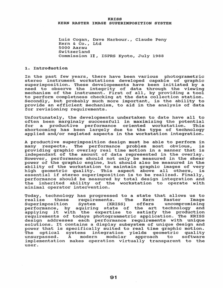
KRISS KERN RASTER IMAGE SUPERIMPOSITION SYSTEM Luis Cogan, Dave Harbour., Claude Peny Kern & Co., Ltd 5000 Aarau switzerland Commission II, ISPRS Kyoto, July 1988 1 .. Introduction In the past few years, there have been various photogrametric stereo instrument workstations developed capable of graphic superimposition. These developements have been initiated by a need to observe the integrity of data through the viewing mechanism of the instrument. First of all, by providing a tool to perform completness checking at the data collection station. Secondly, but probably much more important, is the ability to provide an efficient mechanism, to aid in the analysis of data for revisioning requirements. Unfortunately, the developments undertaken to date have all to often been marginaly successfull in maximizing the potential for a productive performance oriented workstation. This shortcoming has been largely due to the type of technology applied and/or negleted aspects in the workstation integration. A productive superimposition design must be able to perform in many respects. The performance problem most obvious, is providing graphic overlay real time motion in a manner that is independant of the amount of data represented in the overlay. However, performance should not only be measured in the shear power of the graphic engine, but should also be measured in the ability of the workstation to maintain graphic images of very high geometric quality. This aspect above all others, is essential if stereo superimposition is to be realized. Finally, performance should be measured by total design integration and the inherited ability of the workstation to operate with minimal operator intervention. Today, technology has progressed to a state that allows us to realize these requirements. The Kern Raster Image Superimposition System (KRISS) offers uncompromising performance, by aquiring state of the art technology and applying it with the expertise to satisfy the production requirements of todays photogrammetric application. The KRISS design addresses each performance requirements with unique solutions. It contains a display subsystem of unique design and power that is specifically suited to real time graphic motion. The optical systems integration yields geometric quality unsurpassed. A modern modular approach to software implementation makes operation virtually transparent to the user. 91 2. system Overview KRISS is an optional peripheral designed specifically for the Kern DSR-15 analytic plotter. The DSR-15 with KRISS host processor, is a Q-bus MicroVAX operating under MicroVMS.. The KRISS is available in four configurations; stereoscopic viewing with 25 micron resolution, stereoscopic viewing with 50 micron resolution, monoscopic viewing with 25 micron resolution and monoscopic viewing with 50 micron resolution. The KRISS is completly modular in design and can be installed and or upgraded as the system requirements change. 2.1. Configuration System integration was accomplished by expanding the distributed processing architecture of the DSR-15. The'DSR-15 and KRISS are intelligent slave devices to the MicroVAX and perform the dedicated real time processing required in their respective environments. with this distributed approach to processing, the host can maintain functional control of the simultaneous real time tasks while performing the tasks required by the current application. MicroVAX KRISS DSR - 15 Fig 1 DSR-1S with KRISS configuration communications between the MicroVAX and the KRISS display processor is accomplished over a high speed (two megabyte per second maximum) parallel interface that minimizes loading intervals for archived data. This interface is memory mapped on the MicroVAX side with DMA capability on the display processor side. The KRISS is linked to the DSR-15 by virtue of four stage plate positional axis encoder signals. These signals provide input to a dedicated position keeping interface resident on the VME bus of the display processor. By establishing a position feedback loop that is independant of the host processor, KRISS is able to maintain accurate instantaneous stage plate information for continuous image registration. 2.2. Display Processor In order to maximize the capacity of the display processors functional capability; communications, real time loop monitoring, perspective transformation(s) and rasterization are all handled locally" To allow for the maximum flexibility in interfacing with various systems, graphics are recieved by the display processor as vectored data in world coordinates" In addition to this, the display processor maintains a local stroke list for the generation of characters and symbols and thereby eliminating the burden of stroke generation from the host.. Each symbol stroke list is optionaly definable by the user to suit their requirements. The display processor is based on a Motorola 68020 with 68881 floating point coprocessor.. The display processor itself is dual ported onto an auxilIary image bus that is shared'by the image memory and a display generator. Upon receipt of graphic information the display processor will perform the afore mentioned tasks and place the rasterized data into the image memory via the image bus. At that point all image handling is accomplished with minimal intervention on the part of the display processor and is accomplished exclusively on the image bus. RS-232 DSR-15 RS-232 J1JlJlJ MicroVAX Parallel position Keeping Unit DMA Interface I I VME BUS III DISPLAY PROCESSOR III IMAGE BUS 1 I Image Memory Display Generator I Monitor 1 4 or 8 or 16 Mbytes I Monitor 2 Fig. 2 KRISS block diagram 93 2.3. Display Subsystem The concept behind the KRISS display subsystem, is to maintain a raster image of the graphic overlay in physical memory. By virtue of having this graphical image in physical memory the need for repeated data manipulation and/or elabo~ate faceting techniques is eliminated. Each bit of the lmage memory represents one pixel and is equivalent to a nominal photograph area of 25 or 50 microns square, depending on the memory size option selected. Image memory is bitmapped into display memory, a two Megabyte frame buffer (per monitor) which is resident on the display generator. The display memory is updated as required at a rate of 60 hertz. In fact, the actual display memory update is initiated by an interupt issued by the display generator on completion of the vertical sweep. The actual area from the display memory used as a viewport for the display monitor(s) is a region of 1024 by 1024 pixels. The resulting viewport(s) are then displayed on high resolution monochrome monitor(s). These monitors have been manufactured with flat screens. As there is no screen curVature a very good geometric accuracy thoughout the field of view, is provided to the optical system. The entire display subsystem can be conceptualized as, a torus display memory in which the viewport for the monitor is allowed to roam around freely. When the viewport is in transit the display memory is being updated as required, from physical image memory, along the boundary no longer required. Image Memory Display Memory Viewport (monitor display) Fig. 3 Display subsystem Figure number 3 depicts the relationship of the image memory with respect to the the display memory and the selected viewport. 94 3 .. Integration 3 .. 1 .. optical System The superior optical system design of the DSR-15 allowed optimum integration of the KRISS subsystem without any major modifications. This optical design made possible for the image injection to be performed at the front end of the optical system (see fiqure number four). By establishing the image integration at this location in the optical system a superior image geometry was realized. Furthermore, all optical adjustments and zoom are applied after image integration, and thereby influence both images equally_ This simple design integration aspect eliminates the need for repetitious image fitting and registration on the part of the operator. Photogragh Image , Floating Mark I Graphic Image I Beam Splitter 20-200 Micron Diaphram I Objective Beam Splitter I Zoom lx .... 4x J Image Rotation I Image Swap I squint Adjustments I Eyepiece 5x Fig. 4 optical Path with KRISS 95 Objective 3.2. Software Integration The software support system for KRISS was developed with the same modern modular approach as the hardware system. In support of the applications programmming environment, there have been layered device and application libraries written. Therefore, application programs are not concerned with any device specific protocol. This Kern approach to modular software has made the implemention of KRISS with popular applications software packages such as MAPS-200 and DTMCOL both immediate and efficient. Application Programs Application Library Device Library Device Protocol Fig. 5 Software levels 4. Conclusion The design of KRISS was not only accomplished by paying attention to those aspects often neglected and overlooked during system integration, but also in applying todays technology. By utilizing the distributed processing architecture of the DSR-15, KRISS is performance oriented. KRISS was carefully integrated in all respects; the optical, electronic, and software components of the system each compliment the other. The Kern Raster Image Superimpsition System was developed to maximize the potential of stereo superimposition, and will serve as a productive photogrammetric tool today, and in the future. 96

