a AN-385 APPLICATION NOTE •

a
AN-385
APPLICATION NOTE
ONE TECHNOLOGY WAY • P.O. BOX 9106 • NORWOOD, MASSACHUSETTS 02062-9106 • 617/329-4700
Make Wide Temperature Range, Ultralow Drift Accelerometers
Using Low Cost Crystal Ovens
by Charles Kitchin
Commercial crystal ovens have been used for many years to stabilize radio frequency oscillators which need to maintain a near constant frequency over wide temperature ranges. These same products can be used to maintain an accelerometer, such as the ADXL50 and
ADXL05, at a constant operating temperature. This effectively provides a very low drift, wide temperature range acceleration measurement circuit.
The ADXL50 and ADXL05 accelerometers provide a linear voltage output that varies directly with applied acceleration. With the ADXL50, the nominal sensitivity is
19 mV per g centered around a +1.8 volt 0 g offset. The change in output voltage over temperature (i.e., drift) of this offset is very small compared with the amplitude of high g level signals but becomes more significant when the accelerometer is measuring low g levels. In cases where a true dc (i.e., gravity measuring) response is needed, such as when measuring tilt angle, the 0 g offset drift needs to be kept very low.
The crystal oven specified here, an Isotemp #M050570 is available for $15.00 (in 100s), is small—only 3/4" in diameter by 1/2" high, and operates from the same +5 V supply voltage as the accelerometer. This particular model maintains the accelerometer at +70
°
C, which is just right for our lowest cost “J” grade devices specified for operation over the 0
°
C to +70
°
C commercial temperature range. These ovens are available for operation at other temperatures up to +95
°
C and with different supply voltages. For an “A” –40
°
C to +85
°
C industrial grade device, an oven with an operating temperature of +85
°
C should be used; this will provide the greatest overall operating temperature range. Note that, although the oven’s specified tolerance is
±
3
°
C, its typical performance is much better as long as the accelerometer is carefully fitted to the oven as described in this application note.
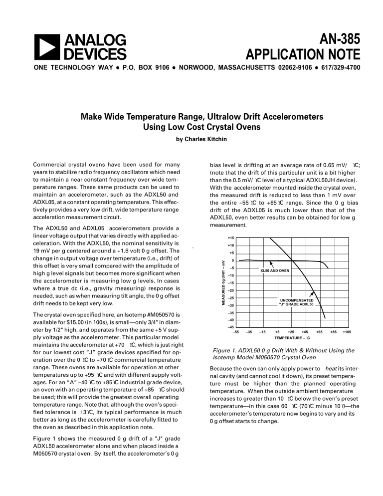
Figure 1 shows the measured 0 g drift of a "J" grade
ADXL50 accelerometer alone and when placed inside a
M050570 crystal oven. By itself, the accelerometer’s 0 g bias level is drifting at an average rate of 0.65 mV/
°
C;
(note that the drift of this particular unit is a bit higher than the 0.5 mV/
°
C level of a typical ADXL50JH device).
With the accelerometer mounted inside the crystal oven, the measured drift is reduced to less than 1 mV over the entire –55
°
C to +65
°
C range. Since the 0 g bias drift of the ADXL05 is much lower than that of the
ADXL50, even better results can be obtained for low g measurement.
+15
+10
+5
0
–5
–10
–15
–20
–25
–30
–35
–40
–45
–55 –35
XL50 AND OVEN
–15
UNCOMPENSATED
"J" GRADE ADXL50
+5 +25 +45
TEMPERATURE –
°
C
+65 +85 +105
Figure 1. ADXL50 0 g Drift With & Without Using the
Isotemp Model M050570 Crystal Oven
Because the oven can only apply power to heat its internal cavity (and cannot cool it down), its preset temperature must be higher than the planned operating temperature. When the outside ambient temperature increases to greater than 10
°
C below the oven’s preset temperature—in this case 60
°
C (70
°
C minus 10
°
)—the accelerometer’s temperature now begins to vary and its
0 g offset starts to change.
The oven has a built-in proportional control that regulates its temperature: as the outside temperature drops, more current is applied to its internal heater to maintain a constant temperature inside the oven. This means that the oven will consume more power at lower temperatures and less at higher approaching zero at its preset temperature. Figure 2 shows the measured current consumption of a typical M050570 (+5 V, 70
°
C) model oven vs. temperature.
A typical low g measurement circuit using the accelerometer/oven combo is shown in Figure 3. In this circuit, low-pass filtering provided by capacitor Cf, reduces the measurement bandwidth to approximately 1 Hz, and lowers the noise floor, improving resolution. The crystal oven and accelerometer are both powered by the same +5 volt supply, although they should be connected to the supply using separate leads. This prevents any transient signals from the current powering the oven from interfering with the accelerometer's circuitry.
600
500
400
300
200
100
0
–55 –35 –15 +5 +25 +45
TEMPERATURE –
°
C
+65 +85 +105
Figure 2. Isotemp Model M050570 Crystal Oven
Typical Current Consumption vs. Temperature
C2
0.022µF
4
2
C1
0.022µF
3
ADXL50 OR ADXL05
1.8V
PRE-AMP
COM
5
6
+3.4V
REF
V
PR
8
V
PR
10
V
IN–
R1
R2
0g OUTPUT – +2.5V
3dB Bw – 10Hz
BUFFER
AMP
R3
C
F
1
9
V
OUT
C3
0.1µF
+5V
+5V
V
OUT
ISOTEMP
M050570
1 +VDC
2 NC
3 0VDC
DEVICE FS MEASUREMENT RANGE* OUTPUT SENSITIVITY BUFFER GAIN
ADXL50
ADXL05
±
10g
±
2g
100mV/g
500mV/g
5.26
2.50
*FS RANGE NUMBERS ARE CONSERVATIVE TO ALLOW FOR V
PR
0g TOLERANCE.
R1
26.1k
40.2k
R2
351k
255k
Figure 3. Low g DC Coupled (Tilt) Circuit Using Crystal Oven Compensation
R3
137k
100k
CF
0.1
µ
F
0.15
µ
F
–2–
USE THERMAL
HEAT SINK COMPOUND
ON TOP & SIDES OF
ACCELEROMETER'S CAN
SEAL AIRSPACE BETWEEN
OUTSIDE OF OVEN AND
TOP OF PRINTED CIRCUIT
BOARD WITH RED RTV
COMPOUND
ISOTEMP
M050570
ADXL50 OR ADXL05
PRINTED CIRCUIT BOARD
Figure 4. Mechanically Mounting the Crystal Oven to the Accelerometer
The circuit can be built on a small card such as the 0.8
″ square ADXL50 evaluation card. After the circuit has been built up and is operating properly, the crystal oven can be installed over the accelerometer as shown in Figure 4. After applying silicon heat sink compound to the top and sides of the accelerometer’s can (being careful not to use too much or get any compound on the leads), slide the oven over the accelerometer until it is firmly seated against the bottom edge of the can.
Then run the oven’s leads through the breadboard and solder them to the bottom side of the board. The oven has three leads: one is +5 V, the center lead is not used, and the third is power supply common (ground). Be sure that the +5 V supply lead used for the oven is a separate wire from that powering the accelerometer. The last step is to seal any air gap between the bottom of the oven and the top of the PC board using red RTV compound or a similar material.
The circuit’s scale factor may be user trimmed for extremely high accuracy by substituting a trim potentiometer and metal film resistor combination for R1.
This adjustment should be made only after the accelerometer’s temperature has settled out at the oven’s preset temperature.
The crystal ovens may be purchased ( and Free samples are available) from Isotemp Research, Inc., P.O. Box
3389, Charlottesville, VA. 22903. Phone: 804-295-3101,
Fax 804-977-1849.
ADXL50HX and ADXL05HX sample packs are available from any Analog Devices sales office or distributor.


