Solution to Tipler P30.54—C.E. Mungan, Spring 2001
advertisement
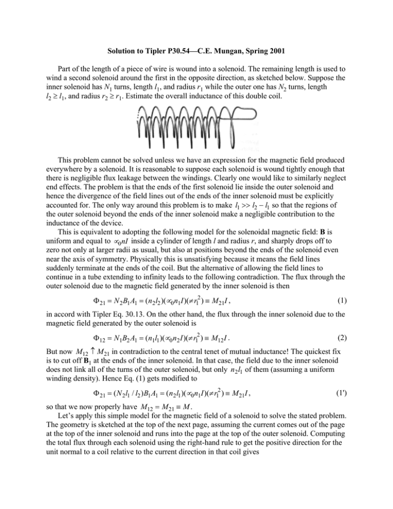
Solution to Tipler P30.54—C.E. Mungan, Spring 2001 Part of the length of a piece of wire is wound into a solenoid. The remaining length is used to wind a second solenoid around the first in the opposite direction, as sketched below. Suppose the inner solenoid has N1 turns, length l1, and radius r1 while the outer one has N2 turns, length l2 ≥ l1, and radius r2 ≥ r1. Estimate the overall inductance of this double coil. This problem cannot be solved unless we have an expression for the magnetic field produced everywhere by a solenoid. It is reasonable to suppose each solenoid is wound tightly enough that there is negligible flux leakage between the windings. Clearly one would like to similarly neglect end effects. The problem is that the ends of the first solenoid lie inside the outer solenoid and hence the divergence of the field lines out of the ends of the inner solenoid must be explicitly accounted for. The only way around this problem is to make l1 >> l2 − l1 so that the regions of the outer solenoid beyond the ends of the inner solenoid make a negligible contribution to the inductance of the device. This is equivalent to adopting the following model for the solenoidal magnetic field: B is uniform and equal to µ 0 nI inside a cylinder of length l and radius r, and sharply drops off to zero not only at larger radii as usual, but also at positions beyond the ends of the solenoid even near the axis of symmetry. Physically this is unsatisfying because it means the field lines suddenly terminate at the ends of the coil. But the alternative of allowing the field lines to continue in a tube extending to infinity leads to the following contradiction. The flux through the outer solenoid due to the magnetic field generated by the inner solenoid is then Φ 21 = N 2 B1 A1 = ( n 2 l2 )(µ 0 n1I )(π r12 ) ≡ M 21I , (1) in accord with Tipler Eq. 30.13. On the other hand, the flux through the inner solenoid due to the magnetic field generated by the outer solenoid is Φ12 = N 1B2 A1 = ( n1l1 )(µ 0 n 2 I )(π r12 ) ≡ M12 I . (2) But now M12 ≠ M 21 in contradiction to the central tenet of mutual inductance! The quickest fix is to cut off B1 at the ends of the inner solenoid. In that case, the field due to the inner solenoid does not link all of the turns of the outer solenoid, but only n 2 l1 of them (assuming a uniform winding density). Hence Eq. (1) gets modified to Φ 21 = ( N 2 l1 / l2 ) B1 A1 = ( n 2 l1 )(µ 0 n1I )(π r12 ) ≡ M 21I , (1') so that we now properly have M12 = M 21 ≡ M . Let’s apply this simple model for the magnetic field of a solenoid to solve the stated problem. The geometry is sketched at the top of the next page, assuming the current comes out of the page at the top of the inner solenoid and runs into the page at the top of the outer solenoid. Computing the total flux through each solenoid using the right-hand rule to get the positive direction for the unit normal to a coil relative to the current direction in that coil gives B2 B1 Φ1 = N 1 ( B1 − B2 ) A1 = ( L1 − M ) I and Φ 2 = N 2 B2 A2 − ( N 2 l1 / l2 ) B1 A1 = ( L2 − M ) I (3) where the self-inductances of each solenoid are L1 = µ 0 N 12π r12 / l1 and L2 = µ 0 N 22π r22 / l2 . (4) Equation (3) is consistent with Tipler Eq. 30.11, noting that the currents I1 and I2 through the two solenoids are in opposite directions. If you like, Eq. (3) says the total flux equals the “self flux” plus the “mutual flux.” Finally, the net flux of the entire device is given by the sum of the fluxes through each coil and hence the overall inductance is N 12 r12 N 22 r22 2 N 1N 2 r12 Φ1 + Φ 2 = L1 + L2 − 2 M = πµ 0 + − L= . l2 l2 I l1 Substituting the numbers given in P30.54 gives L = 7.9 mH. (5)
