the system in response to massive contingencies,
advertisement

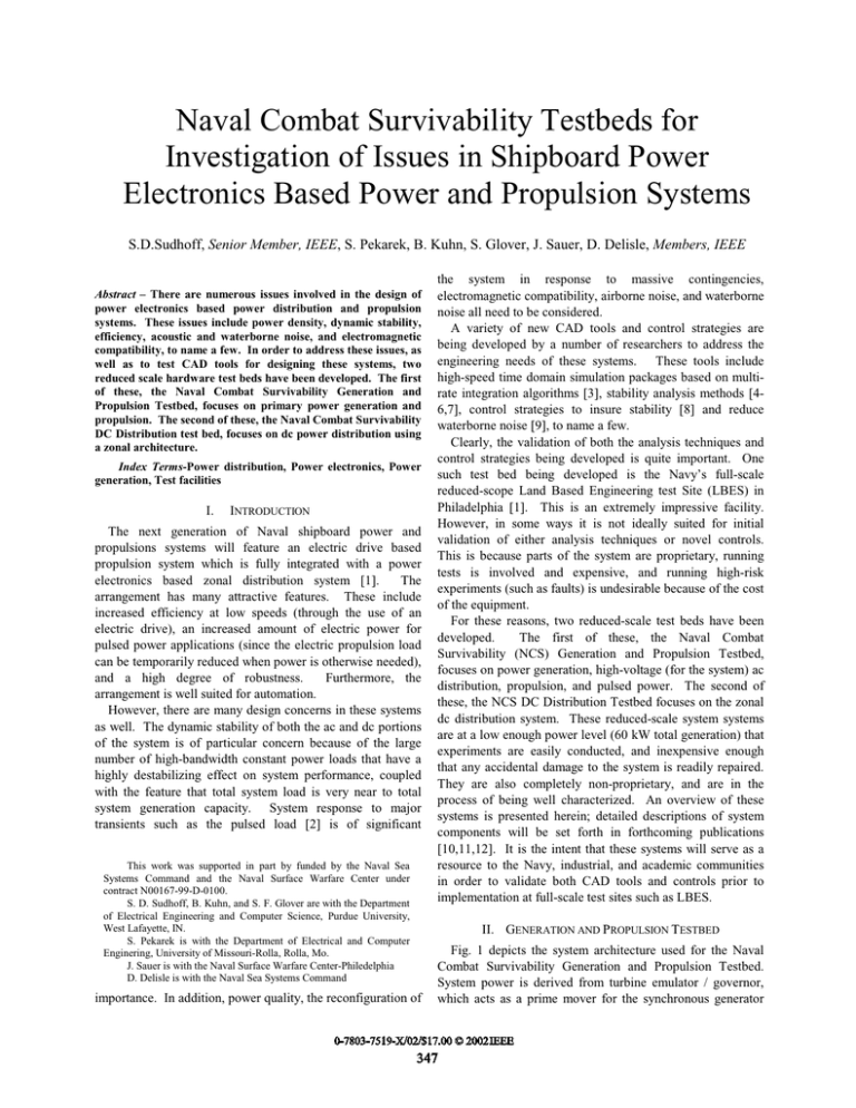
Naval Combat Survivability Testbeds for Investigation of Issues in Shipboard Power Electronics Based Power and Propulsion Systems S.D.Sudhoff, Senior Member, IEEE, S. Pekarek, B. Kuhn, S. Glover, J. Sauer, D. Delisle, Members, IEEE Abstract – There are numerous issues involved in the design of power electronics based power distribution and propulsion systems. These issues include power density, dynamic stability, efficiency, acoustic and waterborne noise, and electromagnetic compatibility, to name a few. In order to address these issues, as well as to test CAD tools for designing these systems, two reduced scale hardware test beds have been developed. The first of these, the Naval Combat Survivability Generation and Propulsion Testbed, focuses on primary power generation and propulsion. The second of these, the Naval Combat Survivability DC Distribution test bed, focuses on dc power distribution using a zonal architecture. Index Terms-Power distribution, Power electronics, Power generation, Test facilities I. INTRODUCTION The next generation of Naval shipboard power and propulsions systems will feature an electric drive based propulsion system which is fully integrated with a power electronics based zonal distribution system [1]. The arrangement has many attractive features. These include increased efficiency at low speeds (through the use of an electric drive), an increased amount of electric power for pulsed power applications (since the electric propulsion load can be temporarily reduced when power is otherwise needed), and a high degree of robustness. Furthermore, the arrangement is well suited for automation. However, there are many design concerns in these systems as well. The dynamic stability of both the ac and dc portions of the system is of particular concern because of the large number of high-bandwidth constant power loads that have a highly destabilizing effect on system performance, coupled with the feature that total system load is very near to total system generation capacity. System response to major transients such as the pulsed load [2] is of significant This work was supported in part by funded by the Naval Sea Systems Command and the Naval Surface Warfare Center under contract N00167-99-D-0100. S. D. Sudhoff, B. Kuhn, and S. F. Glover are with the Department of Electrical Engineering and Computer Science, Purdue University, West Lafayette, IN. S. Pekarek is with the Department of Electrical and Computer Enginering, University of Missouri-Rolla, Rolla, Mo. J. Sauer is with the Naval Surface Warfare Center-Philedelphia D. Delisle is with the Naval Sea Systems Command the system in response to massive contingencies, electromagnetic compatibility, airborne noise, and waterborne noise all need to be considered. A variety of new CAD tools and control strategies are being developed by a number of researchers to address the engineering needs of these systems. These tools include high-speed time domain simulation packages based on multirate integration algorithms [3], stability analysis methods [46,7], control strategies to insure stability [8] and reduce waterborne noise [9], to name a few. Clearly, the validation of both the analysis techniques and control strategies being developed is quite important. One such test bed being developed is the Navy’s full-scale reduced-scope Land Based Engineering test Site (LBES) in Philadelphia [1]. This is an extremely impressive facility. However, in some ways it is not ideally suited for initial validation of either analysis techniques or novel controls. This is because parts of the system are proprietary, running tests is involved and expensive, and running high-risk experiments (such as faults) is undesirable because of the cost of the equipment. For these reasons, two reduced-scale test beds have been developed. The first of these, the Naval Combat Survivability (NCS) Generation and Propulsion Testbed, focuses on power generation, high-voltage (for the system) ac distribution, propulsion, and pulsed power. The second of these, the NCS DC Distribution Testbed focuses on the zonal dc distribution system. These reduced-scale system systems are at a low enough power level (60 kW total generation) that experiments are easily conducted, and inexpensive enough that any accidental damage to the system is readily repaired. They are also completely non-proprietary, and are in the process of being well characterized. An overview of these systems is presented herein; detailed descriptions of system components will be set forth in forthcoming publications [10,11,12]. It is the intent that these systems will serve as a resource to the Navy, industrial, and academic communities in order to validate both CAD tools and controls prior to implementation at full-scale test sites such as LBES. II. GENERATION AND PROPULSION TESTBED importance. In addition, power quality, the reconfiguration of Fig. 1 depicts the system architecture used for the Naval Combat Survivability Generation and Propulsion Testbed. System power is derived from turbine emulator / governor, which acts as a prime mover for the synchronous generator 0-7803-7519-X/02/$17.00 © 2002IEEE 347 37 kW 0 - 460 V l-l rms (max) 0 - 120 Hz 560 V l-l rms ac Governor Exciter Turbine Emulator SM Propulsion Power Converters IM Load Emulator 59 kW HF Pulsed Load (Future Addition) PS 15 kW 3-Phase Bus Figure 1. Power Generation and Propulsion Testbed Architecture. Figure 3. Turbine Emulator and Synchronous Generator depicted in Fig. 2. The primary load on the system is the propulsion system. This consists of the propulsion power converter driving an induction motor and load emulator. Other loads on the system include a passive harmonic filter (HF) and a power supply (PS) that feed the dc distribution system. The pulsed power load will be a future addition to the system. A description of each of the components will now be set forth. 112 kW induction motor drive based dynamometer system. For most studies, this is run in constant speed mode, though dynamics properties can be emulated. The synchronous generator, shown in Figs. 2 and 3, is a Leroy Somer two bearing Alternator part number LSA43.2L7. It is rated for 59 kW (continuous) with an output voltage of 520-590 V, l-l, rms. The machine is equipped with a brushless excitation system and a voltage regulator. The baseline output voltage is 560 V l-l rms. The propulsion system is based around a 37 kW, 1800 rpm, 460 V l-l rms induction motor drive. The induction motor is a Baldor model number ZDM4115T_AM1 machine configured for 460 V operation. Two versions of the drive electronics are shown. The first of these is a conventional uncontrolled rectifier / dc link / two-level converter depicted in Figure 4. The second of these is a multilevel active rectifier / dc link / multi-level inverter depicted in Figure 5. The propulsion drive system is shown in Figure 6; therein it can be seen that the propulsion motor is situated in a sound room so that acoustic measurements can be made. In addition the machine is equipped with accelerometers for vibration analysis. Figure 4. Conventional Propulsion Drive + vc2 iar ibr icr ia ar cr ib a b br c ic + vc1 - g Figure 5. Multi-Level Propulsion Drive Figure 6. Propulsion Motor and Load Emulator Figure 2. Generation System 348 ias +- vas vcs + ibs vbs + - ics The load emulator is a 37 kW induction motor based four-quadrant dynamometer. For some studies, this emulator is programmed to maintain constant speed or torque. In other studies, the load emulator is programmed to produce desired torque-speed characteristics. The harmonic filter is a wye-connected series LC arrangement. The effective capacitance is 50 µF and the inductance is 5.6 mH (rated for 40 A peak, without saturating). It is designed to reduce the effect of the 5th and 7th harmonic components in the system. The power supply is depicted in Figure 7. This 15 kW unit converts power from 560 V l-l rms AC to ~500 V DC. It has a transformer / rectifier front end followed by a buck converter. In can be operated in two modes; first with the buck converter present (in which case the output voltage is regulated) and second with the buck converter removed, so that the output is simply that of an uncontrolled rectifier. Several pulsed power loads are being considered for future additions. The two principal arrangements being considered are a line-commutated converter to charge a capacitor; the second is an uncontrolled converter followed by a dc/dc converter. The selection of the variation for the test system is pending studies. III. DC DISTRIBUTION TESTBED The DC Distribution Testbed is illustrated in Figure 8. Components include the power supplies (PS), the converter modules (CM), an inverter module (IM), motor controller (MC), and a constant power load (CPL). As can be seen, the system consists of two principal busses, port and starboard. Although either power supply may be connected to either bus, each power supply is only connected to a single bus at a time (and never to the same bus). The system is divided into three zones, one for each of the three end-point loads. Each load is fed from both the port and starboard bus through a converter module (CM) and ORing diodes. The converter modules, whose topology is depicted in Figure 9, are designed to reduce a primary bus voltage (approximately 500 V dc) to 420-400 V dc (the voltage droops with load for paralleling purposes). The three loads on the system include the inverter module (IM), motor controller (MC), and constant power load (CPL). The inverter module converts dc to 230 V l-l rms. This source would provide power to ac distribution 349 Figure 8. DC Distribution Testbed iin + il .99 mH is + vin vc - - Lout 1.12 .12 rlout iout + vout 449 F + .128 vout 447 F - - Figure 9: Topology of SSCM. loads. The motor controller is a 3.7 kW induction motor drive. Finally, the CPL is a generic constant power load, which may be set from 0 to 5 kW. IV. INITIAL STUDIES For a comparison of the simulated system to the experimental system constructed in the laboratory, a scenario is run in which the commanded torque of the induction motor drive is stepped from 20 to 200 Nm. During this scenario, the generator is regulating at 560V-ll at 1800RPM and the propulsion drive is at 1500RPM. Figures 10 and 11 illustrate the system waveforms as simulated and as measured experimentally, respectively. The results compare favorably. V. CONCLUSIONS This paper has presented a brief overview of two reduced-scale testbed systems for the validation of CAD tools, analysis techniques, and controls relevant to next generation shipboard power and propulsion systems. This completely non-proprietary system is intended to serve as a resource to the Navy, industrial, and academic communities. In subsequent publications, detailed descriptions of the system components as well as system studies will be set forth. VI. REFERENCES [1] [2] [3] T.J. Mccoy, “Trends in Ship Electric Propulsion,” Panel Session at IEEE PES 2002 Summer Meeting. D.H. Clayton, S.D. Sudhoff, G.F. Grater, “Electric Ship Drive and Power System,” Conference Record of the 2000 Twenty-Fourth International Power Modulator Symposium, June 26-29, 2000, Norfolk, Virginia, pp. 85-88. M. L. Crow and J. G. Chen, “The Multirate Simulation of FACTs Devices in Power System Dynamics,” IEEE Transactions on Power Systems, vol. 11, no. 1, February 1996 Figure 10. Torque Step Study – Simulation Results Figure 11. Torque Step Study – Experimental Results [4] S.D. Sudhoff, D.H. Schmucker, R.A. Youngs, H. J. Hegner, “Stability Analysis of DC Distribution Systems Using Admittance Space Constraints,” Proceedings of The Institute of Marine Engineers All Electric Ship 98, London, September 29-30, 1998 [5] S.D. Sudhoff, S.F. Glover, “Three Dimensional Stability Analysis of DC Power Electronics Based Systems,” Proceedings of the Power Electronics Specialist Conference, Galway, Ireland, June 19-22, 2000, pp. 101-106 [6] S.D. Sudhoff, S.F. Glover, P.T. Lamm, D.H. Schmucker, D.E. Delisle, “Admittance Space Stability Analysis of Power Electronic Systems,” IEEE Transactions on Aerospace and Electronics Systems, Vol. 36, No. 3, July 200, pp. 965-973 [7] M. Belkhayat, O. Wasynczuk, “System Stability Criteria for Electric Ship Propulsion and Ship Service Systems,” Proceedings of the 1998 Naval Symposium on Electric Machinery, October 26-29, 1998, Annapolis, MD. [8] S.D. Sudhoff, K.A. Corzine, S.F. Glover, H.J. Hegner, and H.N. Robey, “DC Link Stabilized Field Oriented Control of Electric Propulsion Systems,” IEEE Transactions on Energy Conversion, Vol. 13, No. 1, March 1998. [9] S.D. Sudhoff, S.M. Nadeson, “Reduction of Inverter Induced Machine Vibration Due to Inverter Non-Idealities Using the Multiple Reference Frame Synchronous Estimator/Regulator,” proceedings of the 3rd Naval Symposium on Electric Machinery, Philadelphia, PA, December 4-7, 2000. [10] Pekarek et. al., “A Hardware Power Electronic-Based Distribution and Propulsion Testbed,” Sixth IASTED International Multi-Conference On Power and Energy System, May 12-15, 2002, Marina del Rey, California, USA [11] S.D. Sudhoff et. al., “Induction Motor Control for Naval Propulsion Applications,” abstract submitted for SAE 2002 Power Systems Conference, Coral Springs, Florida, October 29-31, 2002 [12] S.D. Sudhoff et. al., “Impact of Pulsed Power Loads on Naval Power and Propulsion Systems,” abstract submitted for SAE 2002 Power Systems Conference, Coral Springs, Florida, October 29-31, 2002 350 [13] D.C. Aliprantis et. al., “A Detailed Synchronous Machine Model,” abstract submitted for SAE 2002 Power Systems Conference, Coral Springs, Florida, October 29-31, 2002 [12] S.D. Sudhoff, B. T. Kuhn, P.L. Chapman, D. Aliprantis, “An Advanced Induction Machine Model for Prediction of InverterMachine Interaction,” Power Electronic Specialist Conference, June 17-22, 2001, Vancouver, Canada VII. . BIOGRAPHIES S. D. Sudhoff (S) is currently a Professor of Electrical an Computer Engineering at Purdue University. S. Pekarek (M) is an Assistant Professor at the University of MissouriRolla. B. Kuhn (M) is a Research Engineer at Purdue University. S. F. Glover (M) is a Research Engineer at Purdue University. J. Sauer (M) is with the Naval Surface Warfare Center. D. Delisle (M) is with Naval Sea Systems Command.


