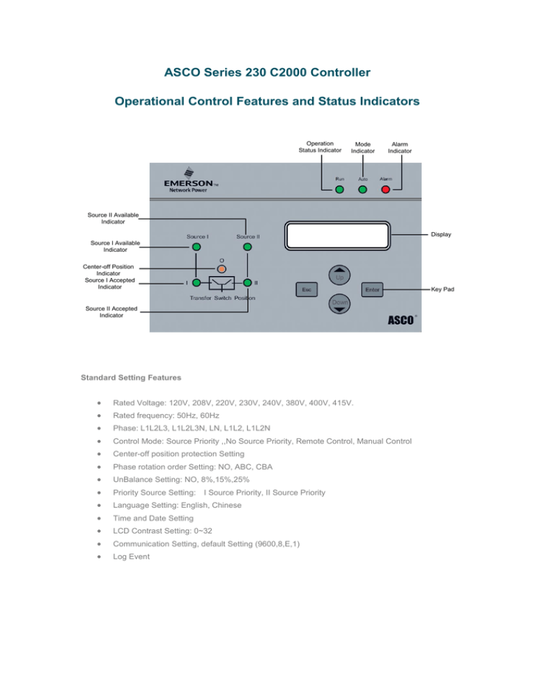
ASCO Series 230 C2000 Controller Operational Control Features and Status Indicators
advertisement

ASCO Series 230 C2000 Controller Operational Control Features and Status Indicators Operation Status Indicator Mode Indicator Alarm Indicator Source II Available Indicator Display Source I Available Indicator Center-off Position Indicator Source I Accepted Indicator Key Pad Source II Accepted Indicator Standard Setting Features Rated Voltage: 120V, 208V, 220V, 230V, 240V, 380V, 400V, 415V. Rated frequency: 50Hz, 60Hz Phase: L1L2L3, L1L2L3N, LN, L1L2, L1L2N Control Mode: Source Priority ,,No Source Priority, Remote Control, Manual Control Center-off position protection Setting Phase rotation order Setting: NO, ABC, CBA UnBalance Setting: NO, 8%,15%,25% Priority Source Setting: Language Setting: English, Chinese Time and Date Setting LCD Contrast Setting: 0~32 Communication Setting, default Setting (9600,8,E,1) Log Event I Source Priority, II Source Priority Voltage & Frequency Sensing Both source I and source II have the same setting as follow: Drop-out voltage is set as 70% ~ 98% of nominal, Drop-out frequency is set as 85% ~98% of nominal, and pickup is 90%~100%, Over is 102% ~ pickup is 85~100% , Over is 102%~120%. 105%. When the over trip is enable, the over voltage function is active. Time Delays T11: 0~3S, Time delay applied to Source I. T12: 0S~5min, Time delay applied when transferring from Position I to Position II. T01:0~3S, Time delay applied to Source II. T21:0S~30min, Time delay applied when transferring from Position II to Position I. T02: 0~5S, Time delay applied to the center-off position O. T03: 0~60min, Time delay to turn off the generator and keep the generator running at no load for some time before shutting / cooling down. Standard Control Contacts Port Port label Port attribute LLP RLY 30Vdc/125Vac, 0.5A≥Rating current≥5mA Normally Closed (NC) & Normally Open (NO) relay outputs. When the load voltage drops to 30% of the rated voltage or load voltage drops to 50Vac, the NC relay output will change to Open, and the NO relay output will change to Closed. DC IN 24VDC±15% DC 24V external Power supply. 30Vdc/125Vac, 0.5A≥Rating current≥5mA Transfer switch status relay output. Normally open. When the controller alarm goes on, the relay contact closes. 30Vdc/125Vac, 0.5A≥Rating current≥5mA Transfer switch position status relay output. Normally open. When switch transfers to center-off, the relay contact closes. 1 2 X3 3 4 5 24V24V+ 1 ALM 2 X4 3 DO1 4 Pin Definition Port Port label Port attribute 5 30Vdc/125Vac, DO2 6 0.5A≥Rating current≥5mA 7 DO3 8 30Vdc/125Vac, 0.5A≥Rating current≥5mA 9 GEN 10 30Vdc/125Vac, 0.5A≥Rating current≥5mA 11 12 485+ 13 485- 14 DGND 15 PGND 16 + Baud rate 485 PORT FIRE 17 - 9600/19200/38400bps, The max connection 32 units. 24Vdc±30%, The polarity must be properly identified, the wrong polarity connection, the fuction should be disable. Normally Closed (NC) & Normally Open (NO) engine relay outputs. During Source 1 Priority mode, when the Source 1 loses power or has some abnormality, the NC relay output changes to open. And the NO relay output changes to closed. Half-duplex 485 interface, 2 line mode, Additional digital grounding and protect grounding ports are available if needed. There should be terminal resistence between 2 lines at the end of the star connection. If the Fire control signal is coming in, the transfer switch will move to center-off position and an alarm will sound. The alarm will continue to sound until the user physically presses any key on the key pad. Passive Digital input Used during Remote operation mode. When signal input is closed, the switch will transfer to Source I. 20 21 Transfer switch position status relay output. Normally open. When the switch transfers to Source II, the relay contact closes. Passive Digital input 19 DI6 Transfer switch position status relay output. Normally open. When the switch transfers to Source I, the relay contact closes. Used during Remote operation mode. When signal input is closed, the switch will transfer to center-off position. 18 DI5 Pin Definition Port Port label Port attribute 22 Passive Digital input 23 DI7 Pin Definition Used during Remote operation mode. When signal input is closed, the switch will transfer to Source II. Remote Control Features Terminal provisions for connecting: The controller receives the external order to transfer from one source to another source when the operating mode is set as remote control. The controller still detects the voltages and frequencies of both sources, but, it will not transfer to another source even though the current source is invalid. The RUN led will blink slowly to indicate current remote control mode.


