IRM-C01PNX Phoenix Port To RJ45 Port Conversion Module User Manual
advertisement

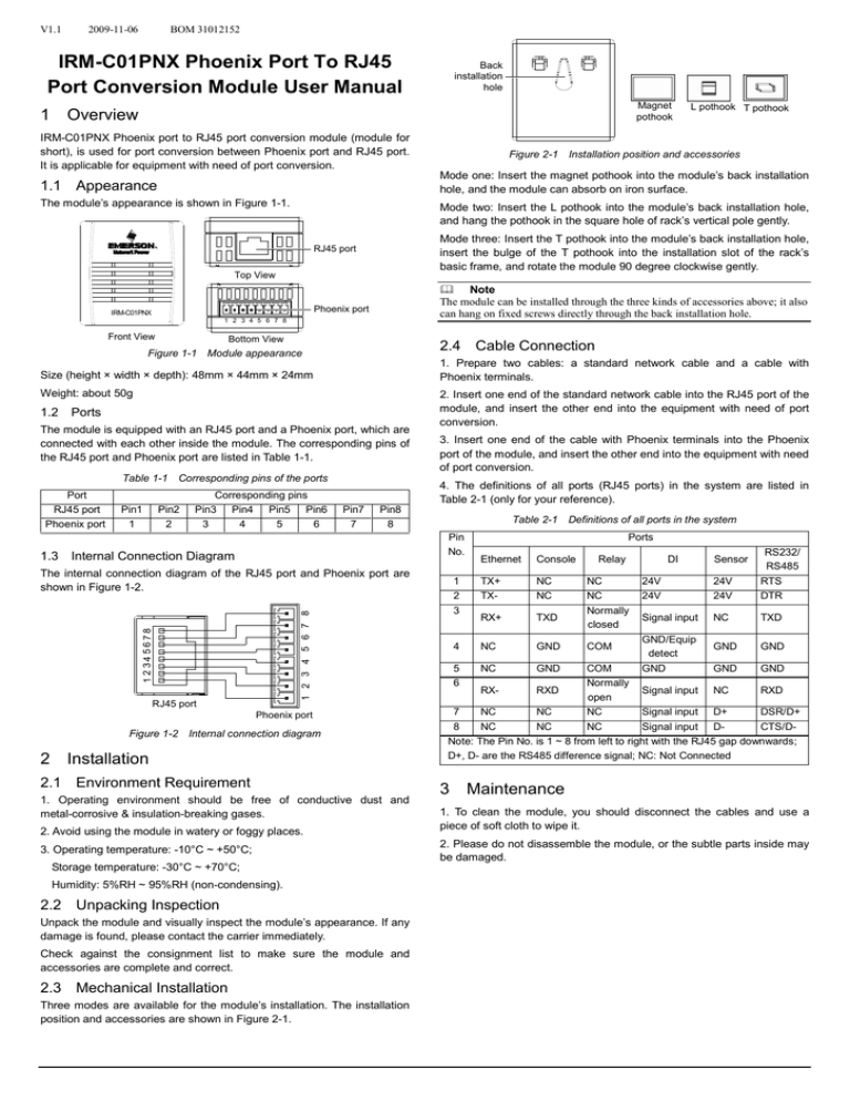
V1.1 2009-11-06 BOM 31012152 IRM-C01PNX Phoenix Port To RJ45 Port Conversion Module User Manual 1 Back installation hole Magnet pothook Overview IRM-C01PNX Phoenix port to RJ45 port conversion module (module for short), is used for port conversion between Phoenix port and RJ45 port. It is applicable for equipment with need of port conversion. The module’s appearance is shown in Figure 1-1. Mode two: Insert the L pothook into the module’s back installation hole, and hang the pothook in the square hole of rack’s vertical pole gently. Mode three: Insert the T pothook into the module’s back installation hole, insert the bulge of the T pothook into the installation slot of the rack’s basic frame, and rotate the module 90 degree clockwise gently. RJ45 port Top View Note The module can be installed through the three kinds of accessories above; it also can hang on fixed screws directly through the back installation hole. Phoenix port IRM-C01PNX 1 2 3 4 5 6 7 8 Front View Bottom View 2.4 Cable Connection Figure 1-1 Module appearance 1. Prepare two cables: a standard network cable and a cable with Phoenix terminals. Size (height × width × depth): 48mm × 44mm × 24mm Weight: about 50g Ports The module is equipped with an RJ45 port and a Phoenix port, which are connected with each other inside the module. The corresponding pins of the RJ45 port and Phoenix port are listed in Table 1-1. Table 1-1 Corresponding pins of the ports Port RJ45 port Phoenix port 1.3 Pin1 1 Figure 2-1 Installation position and accessories Mode one: Insert the magnet pothook into the module’s back installation hole, and the module can absorb on iron surface. 1.1 Appearance 1.2 Pin2 2 Corresponding pins Pin3 Pin4 Pin5 Pin6 3 4 5 6 2. Insert one end of the standard network cable into the RJ45 port of the module, and insert the other end into the equipment with need of port conversion. 3. Insert one end of the cable with Phoenix terminals into the Phoenix port of the module, and insert the other end into the equipment with need of port conversion. 4. The definitions of all ports (RJ45 ports) in the system are listed in Table 2-1 (only for your reference). Pin7 7 Pin8 8 Table 2-1 Definitions of all ports in the system Pin No. Internal Connection Diagram 1 2 34 5 6 7 8 1 2 3 4 5 6 7 8 The internal connection diagram of the RJ45 port and Phoenix port are shown in Figure 1-2. RJ45 port Phoenix port Figure 1-2 Internal connection diagram 2 L pothook T pothook Installation 2.1 Environment Requirement 1. Operating environment should be free of conductive dust and metal-corrosive & insulation-breaking gases. 2. Avoid using the module in watery or foggy places. 3. Operating temperature: -10°C ~ +50°C; Storage temperature: -30°C ~ +70°C; Humidity: 5%RH ~ 95%RH (non-condensing). 2.2 Unpacking Inspection Unpack the module and visually inspect the module’s appearance. If any damage is found, please contact the carrier immediately. Check against the consignment list to make sure the module and accessories are complete and correct. 2.3 Mechanical Installation Three modes are available for the module’s installation. The installation position and accessories are shown in Figure 2-1. Ports Ethernet Console 1 2 3 TX+ TX- NC NC RX+ TXD 4 NC GND 5 6 NC GND 24V 24V 24V 24V RS232/ RS485 RTS DTR Signal input NC TXD GND GND Relay NC NC Normally closed COM DI GND/Equip detect GND Sensor COM GND GND Normally RXRXD Signal input NC RXD open 7 NC NC NC Signal input D+ DSR/D+ 8 NC NC NC Signal input DCTS/DNote: The Pin No. is 1 ~ 8 from left to right with the RJ45 gap downwards; D+, D- are the RS485 difference signal; NC: Not Connected 3 Maintenance 1. To clean the module, you should disconnect the cables and use a piece of soft cloth to wipe it. 2. Please do not disassemble the module, or the subtle parts inside may be damaged.

