DEVICE TOPIC THEORETICAL Electric Power Demonstrator (Our “Bells and Whistles” Demonstrator)
advertisement

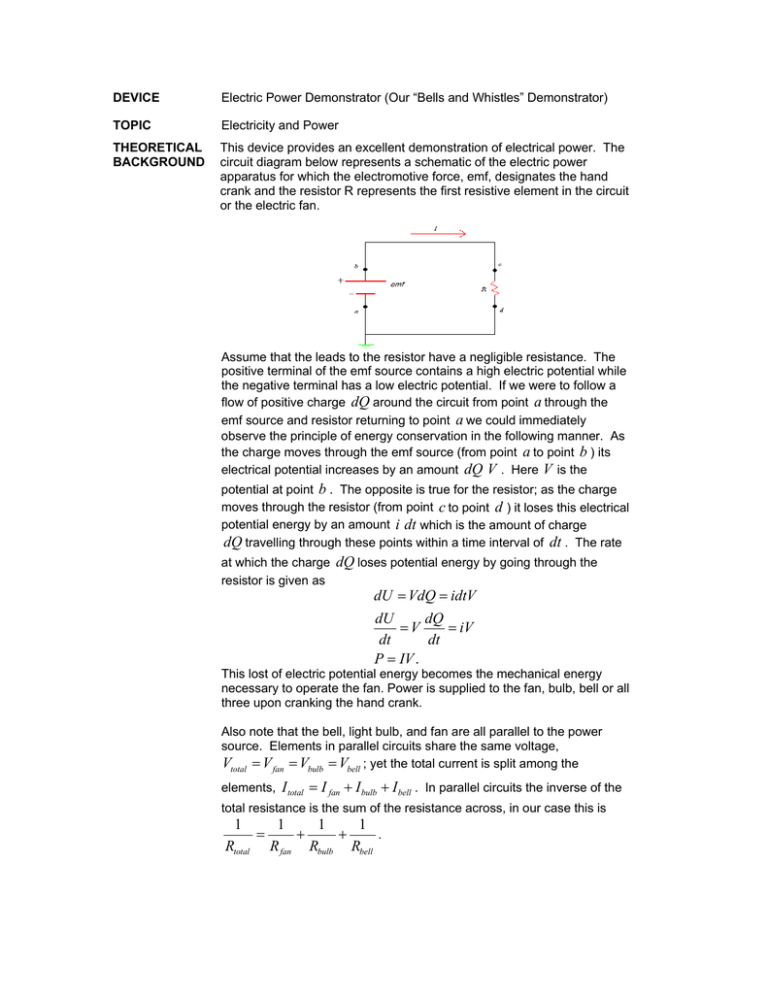
DEVICE Electric Power Demonstrator (Our “Bells and Whistles” Demonstrator) TOPIC Electricity and Power THEORETICAL BACKGROUND This device provides an excellent demonstration of electrical power. The circuit diagram below represents a schematic of the electric power apparatus for which the electromotive force, emf, designates the hand crank and the resistor R represents the first resistive element in the circuit or the electric fan. Assume that the leads to the resistor have a negligible resistance. The positive terminal of the emf source contains a high electric potential while the negative terminal has a low electric potential. If we were to follow a flow of positive charge dQ around the circuit from point a through the emf source and resistor returning to point a we could immediately observe the principle of energy conservation in the following manner. As the charge moves through the emf source (from point a to point b ) its electrical potential increases by an amount dQ V . Here V is the potential at point b . The opposite is true for the resistor; as the charge moves through the resistor (from point c to point d ) it loses this electrical potential energy by an amount i dt which is the amount of charge dQ travelling through these points within a time interval of dt . The rate at which the charge dQ loses potential energy by going through the resistor is given as dU = VdQ = idtV dU dQ =V = iV dt dt P = IV . This lost of electric potential energy becomes the mechanical energy necessary to operate the fan. Power is supplied to the fan, bulb, bell or all three upon cranking the hand crank. Also note that the bell, light bulb, and fan are all parallel to the power source. Elements in parallel circuits share the same voltage, Vtotal = V fan = Vbulb = Vbell ; yet the total current is split among the elements, I total = I fan + I bulb + I bell . In parallel circuits the inverse of the total resistance is the sum of the resistance across, in our case this is 1 1 1 1 . = + + Rtotal R fan Rbulb Rbell DESCRIPTION The “bells and whistles” apparatus is merely a wooden plank holding an electric fan, a light bulb, and a bell combined in a parallel circuit. A hand crank is used to supply electrical power throughout the circuit. Single pole, single throw switches are used to direct the current through the circuit. PROCEDURE 1. Open all the switches except one. Begin to generate electric power to the resistive elements by turning the hand crank. 2. Observe the amount of power is necessary to operate the resistive element. 3. Close the remaining switches and repeat steps 1 through 2. SUGGESTIONS Using the light bulb as a reference one can go through the procedures observing the brightness or dimness of the bulb as the switches are opened and then closed.


