Evolution of wrinkles in hard films on soft substrates *
advertisement

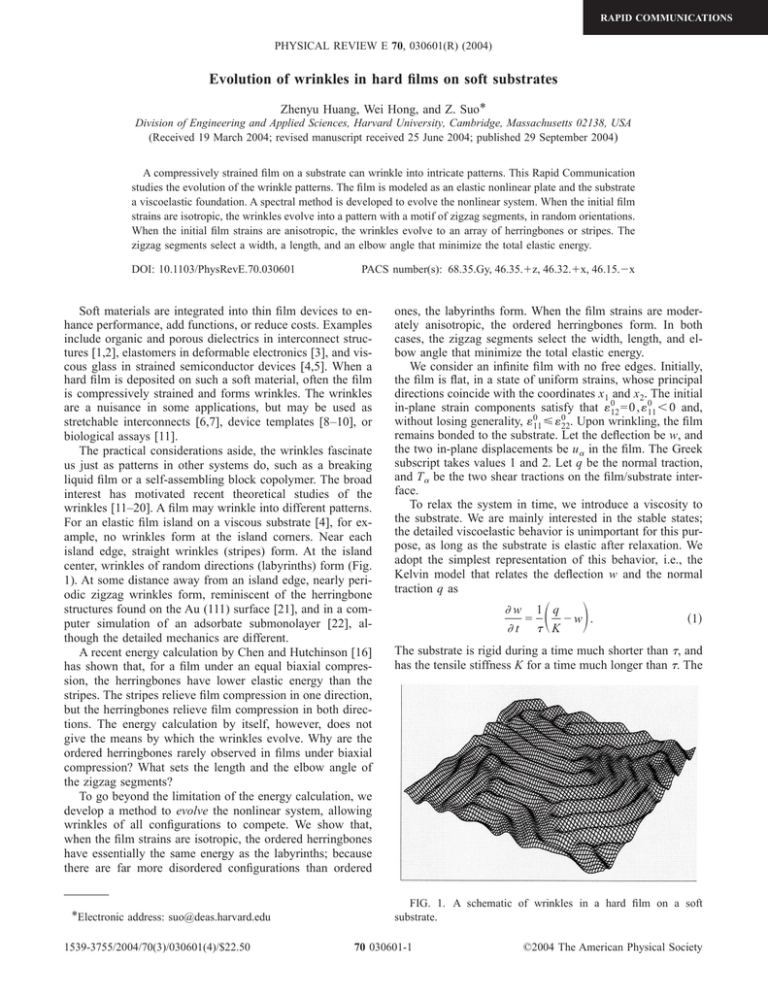
RAPID COMMUNICATIONS PHYSICAL REVIEW E 70, 030601(R) (2004) Evolution of wrinkles in hard films on soft substrates Zhenyu Huang, Wei Hong, and Z. Suo* Division of Engineering and Applied Sciences, Harvard University, Cambridge, Massachusetts 02138, USA (Received 19 March 2004; revised manuscript received 25 June 2004; published 29 September 2004) A compressively strained film on a substrate can wrinkle into intricate patterns. This Rapid Communication studies the evolution of the wrinkle patterns. The film is modeled as an elastic nonlinear plate and the substrate a viscoelastic foundation. A spectral method is developed to evolve the nonlinear system. When the initial film strains are isotropic, the wrinkles evolve into a pattern with a motif of zigzag segments, in random orientations. When the initial film strains are anisotropic, the wrinkles evolve to an array of herringbones or stripes. The zigzag segments select a width, a length, and an elbow angle that minimize the total elastic energy. DOI: 10.1103/PhysRevE.70.030601 PACS number(s): 68.35.Gy, 46.35.⫹z, 46.32.⫹x, 46.15.⫺x Soft materials are integrated into thin film devices to enhance performance, add functions, or reduce costs. Examples include organic and porous dielectrics in interconnect structures [1,2], elastomers in deformable electronics [3], and viscous glass in strained semiconductor devices [4,5]. When a hard film is deposited on such a soft material, often the film is compressively strained and forms wrinkles. The wrinkles are a nuisance in some applications, but may be used as stretchable interconnects [6,7], device templates [8–10], or biological assays [11]. The practical considerations aside, the wrinkles fascinate us just as patterns in other systems do, such as a breaking liquid film or a self-assembling block copolymer. The broad interest has motivated recent theoretical studies of the wrinkles [11–20]. A film may wrinkle into different patterns. For an elastic film island on a viscous substrate [4], for example, no wrinkles form at the island corners. Near each island edge, straight wrinkles (stripes) form. At the island center, wrinkles of random directions (labyrinths) form (Fig. 1). At some distance away from an island edge, nearly periodic zigzag wrinkles form, reminiscent of the herringbone structures found on the Au (111) surface [21], and in a computer simulation of an adsorbate submonolayer [22], although the detailed mechanics are different. A recent energy calculation by Chen and Hutchinson [16] has shown that, for a film under an equal biaxial compression, the herringbones have lower elastic energy than the stripes. The stripes relieve film compression in one direction, but the herringbones relieve film compression in both directions. The energy calculation by itself, however, does not give the means by which the wrinkles evolve. Why are the ordered herringbones rarely observed in films under biaxial compression? What sets the length and the elbow angle of the zigzag segments? To go beyond the limitation of the energy calculation, we develop a method to evolve the nonlinear system, allowing wrinkles of all configurations to compete. We show that, when the film strains are isotropic, the ordered herringbones have essentially the same energy as the labyrinths; because there are far more disordered configurations than ordered *Electronic address: suo@deas.harvard.edu 1539-3755/2004/70(3)/030601(4)/$22.50 ones, the labyrinths form. When the film strains are moderately anisotropic, the ordered herringbones form. In both cases, the zigzag segments select the width, length, and elbow angle that minimize the total elastic energy. We consider an infinite film with no free edges. Initially, the film is flat, in a state of uniform strains, whose principal directions coincide with the coordinates x1 and x2. The initial 0 0 = 0 , 11 ⬍ 0 and, in-plane strain components satisfy that 12 0 0 without losing generality, 11 艋 22. Upon wrinkling, the film remains bonded to the substrate. Let the deflection be w, and the two in-plane displacements be u␣ in the film. The Greek subscript takes values 1 and 2. Let q be the normal traction, and T␣ be the two shear tractions on the film/substrate interface. To relax the system in time, we introduce a viscosity to the substrate. We are mainly interested in the stable states; the detailed viscoelastic behavior is unimportant for this purpose, as long as the substrate is elastic after relaxation. We adopt the simplest representation of this behavior, i.e., the Kelvin model that relates the deflection w and the normal traction q as 冉 冊 w 1 q = −w . t K 共1兲 The substrate is rigid during a time much shorter than , and has the tensile stiffness K for a time much longer than . The FIG. 1. A schematic of wrinkles in a hard film on a soft substrate. 70 030601-1 ©2004 The American Physical Society RAPID COMMUNICATIONS PHYSICAL REVIEW E 70, 030601(R) (2004) HUANG, HONG, AND SUO shear behavior of the substrate is taken to be linearly elastic 共2兲 T␣ = Su␣ , where S is the shear stiffness. Shear viscosity is neglected because it serves no purpose in this model. Shear elasticity, however, plays a crucial role in setting the two-dimensional wrinkle patterns, as will be discussed later. Because the wrinkle amplitude is small compared to the wavelength, the elastic film is accurately modeled by the von Karman nonlinear plate theory [23]. The membrane strains ␣ have three contributions: the initial strains, the gradients of the in-plane displacements, and the rotation caused by the deflection, namely, 0 + ␣ = ␣ 冉 冊 1 u␣ u 1 w w + + . 2 x x␣ 2 x␣ x 共3兲 Hooke’s law relates the membrane forces N␣ to the membrane strains N␣ = Eh 关共1 − 兲␣ + ␥␥␦␣兴, 1 − 2 共4兲 where h is the thickness, E Young’s modulus, and Poisson’s ratio of the film. A repeated Greek subscript implies summation over 1 and 2. The in-plane force balance of a plate element requires that N␣/ x = T␣ . 共5兲 The out-of-plane force balance and the moment balance of a plate element requires that q=− 冉 冊 w 4w Eh3 + N␣ . 共6兲 2 x␣ 12共1 − 兲 x␣ x␣ x x x Equations (1)–(6) evolve the deflection, w共x1 , x2 , t兲, along with all the other fields. Two types of analytical results are obtained readily. First, a linear perturbation analysis shows that an initial imperfec0 exceeds that of a tion can amplify if the magnitude of 11 −1 冑 critical strain, c = −关 3B共1 + 兲兴 . The dimensionless number B = 关E / 共1 − 2兲兴 / Kh measures the relative stiffness of the film to the substrate. As expected, the critical strain has a small magnitude for a stiff film on a compliant substrate. Second, the wrinkles, if constrained to be an array of stripes along the x2 axis, will equilibrate to a sinusoidal deflection field, with wavelength e = 2h共B / 12兲1/4 and amplitude Ae 0 = h冑共2 / 3兲共11 / c − 1兲. This equilibrium state is readily understood. The stripe wrinkles relieve the membrane compression, but bend the film and distort the substrate. A family of self-similar wrinkles, with a fixed ratio of amplitude and wavelength, all relieve the same amount of the membrane compression. Large wrinkles have low bending energy, but small wrinkles have low substrate energy. Consequently, the wrinkles select an intermediate wrinkle size to minimize the total elastic energy. The substrate tensile stiffness K is significant. Were the substrate purely viscous, the substrate would store no elastic energy, and the film bending energy would drive the wrinkles to coarsen indefinitely. FIG. 2. Time sequence of wrinkle patterns, starting from a random initial deflection imperfection. The initial strain field is equal biaxial, 011 = 022 = −0.02. We evolve wrinkle patterns in a square cell in the plane 共x1 , x2兲. Periodic boundary conditions replicate the cell to the entire plane. The cell is subdivided into grids. Values of the functions at the grid points are evolved in time. The cell must be large enough to accommodate many zigzag segments, and the grid spacing must be small enough to resolve the individual elbows. An inspection of Eqs. (1)–(6) indicates two difficulties: the nonlinear terms and the spatial differentiations. A spectral method [24] deals with the two difficulties in separate planes. It calculates the nonlinear terms in the 共x1 , x2兲 plane, and the spatial differentiations in the Fourier plane, where the spatial differentiations become multiplications with the wave vector. At each time step, the two planes communicate via the fast Fourier transform and its inverse. All calculations are carried out with B = 1000, = 0.3, and S / K = 1 / 6. The critical strain is c ⬇ −0.014, and the equilibrium wavelength for stripe wrinkles is e ⬇ 19h. Figure 2 displays the deflection w in the plane 共x1 , x2兲 at several times. A gray scale is used: a bright spot represents a crest and a dark spot a trough. The initial film strains are 0 0 = 22 = −0.02. For this example, each side of the cell is 11 32e long, and contains 256 grid points. The initial deflection is random, with the magnitude less than 0.025h. The time increment is 0.2. (Cell and grid sizes, as well as the time increment, have been varied to ascertain numerical convergence.) The wrinkles evolve into a pattern with a motif of zigzag segments. When the deflection is small, a crest bends equally in all directions, like a spherical cap. A large deflection breaks this symmetry: the crest bends only in one direction, like a cylindrical surface. This symmetry breaking has a geometric origin: a flat sheet can bend to a cylindrical surface with no membrane strain, but can only bend to a spherical surface with severe membrane strains. The segments rapidly attain the equilibrium width, which is close to the 030601-2 RAPID COMMUNICATIONS PHYSICAL REVIEW E 70, 030601(R) (2004) EVOLUTION OF WRINKLES IN HARD FILMS ON SOFT… FIG. 5. Total elastic energy as a function of the herringbone period. FIG. 3. Patterns at time t = 20000, started from a random initial deflection imperfection, under different biaxial strains. In all cases, 011 = −0.035. wavelength e of the equilibrium stripes. The segments attain a length several times e, forming labyrinths with no long range order. Figure 3 shows four stable patterns for films with different 0 0 initial strains. In each case, 11 = −0.035, but 22 takes a dif0 ferent value. When 22 = −0.035 (not shown in Fig. 3), the 0 system is isotropic, and the labyrinths form. When 22 = −0.027, the symmetry is broken, and nearly aligned herringbones form, with nearly 90° elbow angles. Note the dislocationlike imperfection, where one herringbone is wedged 0 0 between two other herringbones. When 22 = −0.02 and 22 = −0.018, the herringbones still form, but with obtuse elbow 0 = −0.015, stripes form. angles. When 22 Figure 4 plots the elastic energy stored in the system as a function of time. Initially, the film is under equal biaxial FIG. 4. The total energies for three patterns as functions of time. 0 0 strains 11 = 22 = −0.02; all the elastic energy is stored by the film compression, with the energy per unit area U0 0 2 = Eh共11 兲 / 共1 − 兲. The total energy per unit area, Utotal, reduces over time. The three curves correspond to time sequences started from different initial conditions. When the initial condition is a random deflection field, wrinkles evolve into labyrinths. When the initial condition is a sinusoidal deflection field with wavelength 13.6h and a small amplitude, the wrinkles evolve into the equilibrium stripes with the wavelength e ⬇ 19h. When the initial deflection is an array of nascent herringbones, of period H = 5.6h, wrinkles evolve into equilibrated herringbones. The herringbones and the labyrinths approach essentially the same energy, which is lower than that of the stripes. The labyrinths are merely disordered herringbones; they relieve the film compression in all directions, but have no energy to order. Figure 5 plots the total energy as a function of the her0 ringbone period H. Again, the initial film strains are 11 0 = 22 = −0.02. Divide the computational cell into horizontal segments, each with height H in the x2 direction. In the alternate segments prescribe the initial deflection field w = A cos关冑2共x1 ± x2兲 / e兴, with a small amplitude A. When H is small, the density of the elbows is high. When H is large, the film compression along the arms is unrelaxed. Consequently, herringbones of an intermediate period minimize the total energy. The substrate shear stiffness S plays an essential role in equilibrating the two-dimensional wrinkle patterns. Were the substrate shear stiffness absent, the compression along the length of a set of segments would be relaxed by the bending of a set of neighboring segments oriented in a different direction. Consequently, the segment length would coarsen indefinitely. In summary, under biaxial compression, a hard film on a soft substrate wrinkles with the motif of zigzag segments. Two kinds of symmetry are broken. First, a crest bends into 030601-3 RAPID COMMUNICATIONS PHYSICAL REVIEW E 70, 030601(R) (2004) HUANG, HONG, AND SUO a spherical surface for a small deflection, and bends into a cylindrical surface for a large deflection, resulting in the segments. Second, the segments form labyrinths when the initial membrane strains are isotropic, and form aligned herringbones or stripes when the initial membrane strains are anisotropic. Two lengths emerge. The segments reach an equilibrium width to compromise the film bending and the substrate deflection, and an equilibrium length to compromise the elbow density and the substrate shear. The elbow angle depends on the degree of anisotropy of the membrane strains. [1] S. J. Martin, J. P. Godschalx, M. E. Mills, E. O. Shaffer II, and P. H. Townsend, Adv. Mater. (Weinheim, Ger.) 12, 1769 (2000). [2] F. Iacopi, S. H. Brongersma, and K. Maex, Appl. Phys. Lett. 82, 1380 (2003). [3] S. P. Lacour, S. Wagner, Z. Y. Huang, and Z. Suo, Appl. Phys. Lett. 82, 2404 (2003). [4] H. Yin, R. Huang, K. D. Hobart, Z. Suo, T. S. Kuan, C. K. Inoki, S. R. Shieh, T. S. Duffy, F. J. Kub, and J. C. Sturm, J. Appl. Phys. 91, 9716 (2002). [5] F. Liu, P. Rugheimer, E. Mateeva, D. E. Savage, and M. G. Lagally, Nature (London) 416, 498 (2002). [6] M. Watanabe, H. Shirai, and T. Hirai, J. Appl. Phys. 92, 4631 (2002). [7] S. P. Lacour, J. Jones, Z. Suo, and S. Wagner. IEEE Electron Device Lett. 25, 179 (2004). [8] N. Bowden, S. Brittain, A. G. Evans, J. W. Hutchinson, and G. M. Whitesides, Nature (London) 393, 146 (1998). [9] N. Bowden, W. T. S. Huck, K. E. Paul, and G. M. Whitesides, Appl. Phys. Lett. 75, 2557 (1999). [10] P. J. Yoo, K. Y. Suh, S. Y. Park, and H. H. Lee, Adv. Mater. (Weinheim, Ger.) 14, 1383 (2002). [11] E. Cerda, K. Ravi-Chandar, and L. Mahadevan, Nature (London) 419, 579 (2002); E. Cerda and L. Mahadevan, Phys. Rev. Lett. 90, 074302 (2003). [12] F. Brochard-Wyart and P. G. de Gennes, Science 300, 441 (2003). [13] W. T. S. Huck, N. Bowden, P. Onck, T. Pardoen, J. W. Hutchinson, and G. M. Whitesides, Langmuir 16, 3497 (2000). [14] J. Groenewold, Physica A 298, 32 (2001). [15] K. Niu and R. Talreja, J. Eng. Mech. 125, 875 (1999). [16] X. Chen and J. W. Hutchinson, Scr. Mater. 50, 797 (2004); J. Appl. Mech. (to be published). [17] N. Sridhar, D. J. Srolovitz, and Z. Suo, Appl. Phys. Lett. 78, 2482 (2001). [18] R. Huang and Z. Suo, J. Appl. Phys. 91, 1135 (2002). [19] N. Sridhar, D. J. Srolovitz, and B. N. Cox, Acta Mater. 50, 2547 (2002). [20] L. B. Freund and S. Suresh, Thin Film Materials (Cambridge University Press, Cambridge, 2003). [21] S. Narasimhan and D. Vanderbilt, Phys. Rev. Lett. 69, 1564 (1992). [22] Y. F. Gao, W. Lu, and Z. Suo, Acta Mater. 50, 2297 (2002). [23] L. D. Landau and E. M. Lifshitz, Theory of Elasticity (Pergamon, London, 1959). [24] L.-Q. Chen and J. Shen, Comput. Phys. Commun. 108, 147 (1998). The authors are grateful for the support by the DOE through Grant No. DE-FG02-03ER46091, by the ONR through a MURI subcontract from the University of California at Santa Barbara, and by the Division of Engineering and Applied Sciences at Harvard. Discussions with J.W. Hutchinson were valuable. 030601-4


