The power budget is given by Attenuation-Limited Fiber Length - SOLUTION
advertisement
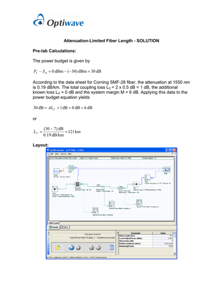
Attenuation-Limited Fiber Length - SOLUTION Pre-lab Calculations: The power budget is given by PT − S R = 0 dBm − (−30) dBm = 30 dB According to the data sheet for Corning SMF-28 fiber, the attenuation at 1550 nm is 0.19 dB/km. The total coupling loss LC = 2 x 0.5 dB = 1 dB, the additional known loss LA = 0 dB and the system margin M = 6 dB. Applying this data to the power budget equation yields 30 dB = AL F + 1 dB + 0 dB + 6 dB or LF = (30 − 7) dB = 121 km 0.19 dB/km Layout: Simulation: The Optical Power Meter Visualizers clearly show the optical power droping along the link. This confirms that the optical fiber plus the optical attenuation have introduced 30 dB of loss. The fiber loss is 23 dB. The next figure shows the BER visualizer output. The eye diagram indicates that the receiver input includes a noticeable level of noise, but that the Q factor is still close to the design level of 6. The eye diagram at L=121 km. Q = 6.06 At 125% of the design length ( L = 121 km x 1.25 = 151 km ), the eye diagram has completely degraded . It is clear from both the eye diagram and the Q factor that this system will not function. The eye diagram at L = 151 km. Q is not measurable. The final figure shows the result if the fiber length remains at the attenuation limit, but the bit rate is increased to 10 Gb/s. The result is again unsatisfactory because the sensitivity of the receiver decreases with increased bit rate. Receiver sensitivity is the subject of a later exercise. The eye diagram at L = 121 km for 10 GB/s system. The up limit of this systems performance can be simulated by setting the attenuation to 1dB to account for connector loss only (i.e. the system margin has been removed). If there are no other unforeseen losses, the BER improves dramatically and the Q value is about 23. In reality, a system margin must always be included.

