FUSIBLE METAL FILM RESISTOR
advertisement
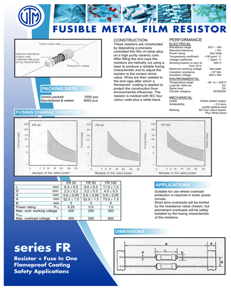
FUSIBLE METAL FILM RESISTOR CONSTRUCTION PACKING DATA Ammo packed Bandoliered & reeled 1000 pcs 5000 pcs These resistors are constructed by depositing a precisely controlled thin film of metal alloy on a high purity ceramic core. After fitting the end caps the resistors are helically cut using a laser to produce a reliable fusing characteristic and to adjust the resistor to the correct ohmic value. Wires are then welded to the end caps after which a flameproof coating is applied to protect the construction from environmental influences. The resistor is marked with IEC four colour code plus a white band. FR 25 6.3 ± 0.5 2.3 ± 0.3 0.6 ± 0.05 52.5 ± 1.5 5 0.25 200 FR 50 9.0 ± 0.5 3.2 ± 0.3 0.6 ± 0.05 52.5 ± 1.5 5 0.5 250 FR 100 11.5 ± 1.0 4.5 ± 0.5 0.8 ± 0.05 73.0 ± 1.5 5 1.0 300 400 500 600 DIMENSIONS series FR Resistor + Fuse In One Flameproof Coating Safety Applications ELECTRICAL Resistance range R27 – 1K0 Standard tolerance ± 5% Power rating See table ±100 ppm/ °C Temperature coefficient Voltage coefficient < 1ppm / V Derating linearly to zero at 200°C from 70°C See table Maximum working voltage 4 >10 MW Insulation resistance Insulation voltage 500 V Min ENVIRONMENTAL Temperature range Load life 1000 hrs Damp heat Climatic category MECHANICAL Leads Solderability Marking FUSING CHARACTERISTICS L mm D mm d mm A mm B mm Power rating P70 Max. cont. working voltage Vrms Max. overload voltage V PERFORMANCE - 55° to + 200°C 5% 5% 50/200/56 Solder plated copper < 2.5 secs (solder globule test) IEC four colour bands Plus White (fuse) APPLICATIONS Suitable for use where overload protection is required in lower power circuits. Short term overloads will be limited by the resistance value chosen, but permanent overloads will be safely isolated by the fusing characteristic of the resistors.


