Optimizing the superlens: Manipulating geometry to enhance the resolution
advertisement

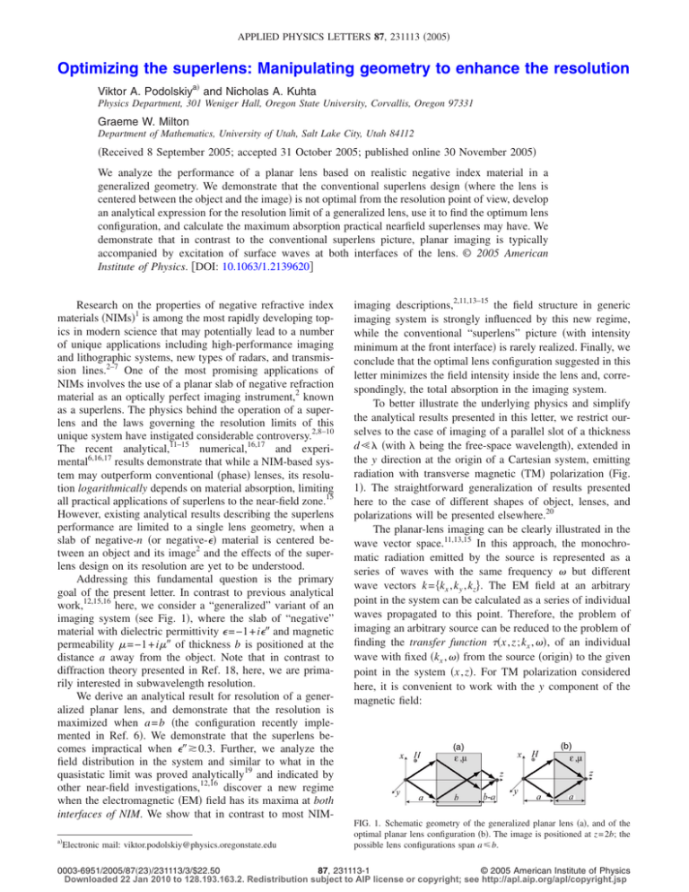
APPLIED PHYSICS LETTERS 87, 231113 共2005兲 Optimizing the superlens: Manipulating geometry to enhance the resolution Viktor A. Podolskiya兲 and Nicholas A. Kuhta Physics Department, 301 Weniger Hall, Oregon State University, Corvallis, Oregon 97331 Graeme W. Milton Department of Mathematics, University of Utah, Salt Lake City, Utah 84112 共Received 8 September 2005; accepted 31 October 2005; published online 30 November 2005兲 We analyze the performance of a planar lens based on realistic negative index material in a generalized geometry. We demonstrate that the conventional superlens design 共where the lens is centered between the object and the image兲 is not optimal from the resolution point of view, develop an analytical expression for the resolution limit of a generalized lens, use it to find the optimum lens configuration, and calculate the maximum absorption practical nearfield superlenses may have. We demonstrate that in contrast to the conventional superlens picture, planar imaging is typically accompanied by excitation of surface waves at both interfaces of the lens. © 2005 American Institute of Physics. 关DOI: 10.1063/1.2139620兴 Research on the properties of negative refractive index materials 共NIMs兲1 is among the most rapidly developing topics in modern science that may potentially lead to a number of unique applications including high-performance imaging and lithographic systems, new types of radars, and transmission lines.2–7 One of the most promising applications of NIMs involves the use of a planar slab of negative refraction material as an optically perfect imaging instrument,2 known as a superlens. The physics behind the operation of a superlens and the laws governing the resolution limits of this unique system have instigated considerable controversy.2,8–10 The recent analytical,11–15 numerical,16,17 and experimental6,16,17 results demonstrate that while a NIM-based system may outperform conventional 共phase兲 lenses, its resolution logarithmically depends on material absorption, limiting all practical applications of superlens to the near-field zone.15 However, existing analytical results describing the superlens performance are limited to a single lens geometry, when a slab of negative-n 共or negative-⑀兲 material is centered between an object and its image2 and the effects of the superlens design on its resolution are yet to be understood. Addressing this fundamental question is the primary goal of the present letter. In contrast to previous analytical work,12,15,16 here, we consider a “generalized” variant of an imaging system 共see Fig. 1兲, where the slab of “negative” material with dielectric permittivity ⑀ = −1 + i⑀⬙ and magnetic permeability = −1 + i⬙ of thickness b is positioned at the distance a away from the object. Note that in contrast to diffraction theory presented in Ref. 18, here, we are primarily interested in subwavelength resolution. We derive an analytical result for resolution of a generalized planar lens, and demonstrate that the resolution is maximized when a = b 共the configuration recently implemented in Ref. 6兲. We demonstrate that the superlens becomes impractical when ⑀⬙ ⲏ 0.3. Further, we analyze the field distribution in the system and similar to what in the quasistatic limit was proved analytically19 and indicated by other near-field investigations,12,16 discover a new regime when the electromagnetic 共EM兲 field has its maxima at both interfaces of NIM. We show that in contrast to most NIMa兲 Electronic mail: viktor.podolskiy@physics.oregonstate.edu imaging descriptions,2,11,13–15 the field structure in generic imaging system is strongly influenced by this new regime, while the conventional “superlens” picture 共with intensity minimum at the front interface兲 is rarely realized. Finally, we conclude that the optimal lens configuration suggested in this letter minimizes the field intensity inside the lens and, correspondingly, the total absorption in the imaging system. To better illustrate the underlying physics and simplify the analytical results presented in this letter, we restrict ourselves to the case of imaging of a parallel slot of a thickness d Ⰶ 共with being the free-space wavelength兲, extended in the y direction at the origin of a Cartesian system, emitting radiation with transverse magnetic 共TM兲 polarization 共Fig. 1兲. The straightforward generalization of results presented here to the case of different shapes of object, lenses, and polarizations will be presented elsewhere.20 The planar-lens imaging can be clearly illustrated in the wave vector space.11,13,15 In this approach, the monochromatic radiation emitted by the source is represented as a series of waves with the same frequency but different wave vectors k = 兵kx , ky , kz其. The EM field at an arbitrary point in the system can be calculated as a series of individual waves propagated to this point. Therefore, the problem of imaging an arbitrary source can be reduced to the problem of finding the transfer function 共x , z ; kx , 兲, of an individual wave with fixed 共kx , 兲 from the source 共origin兲 to the given point in the system 共x , z兲. For TM polarization considered here, it is convenient to work with the y component of the magnetic field: FIG. 1. Schematic geometry of the generalized planar lens 共a兲, and of the optimal planar lens configuration 共b兲. The image is positioned at z = 2b; the possible lens configurations span a 艋 b. 0003-6951/2005/87共23兲/231113/3/$22.50 87, 231113-1 © 2005 American Institute of Physics Downloaded 22 Jan 2010 to 128.193.163.2. Redistribution subject to AIP license or copyright; see http://apl.aip.org/apl/copyright.jsp 231113-2 Appl. Phys. Lett. 87, 231113 共2005兲 Podolskiy, Kuhta, and Milton ⌬ · ␦ = 4 , FIG. 2. 共Color online兲 Transfer functions in 共a兲 and out 共b兲 obtained from exact calculations 共curves兲, and from Eqs. 共2兲 and 共3兲 共symbols兲; optimal and symmetric lens configurations with various absorptions are shown: Black 共solid; squares兲: a = b = 0.35, ⑀⬙ = 10−3, ⬙ = 10−6; red 共dashed; stars兲 a = b = 0.35, ⑀⬙ = ⬙ = 10−6; green 关dashed-dotted; triangles兴: a = b / 2 = 0.35, ⑀⬙ = 10−3, ⬙ = 10−6; red 共dash-dot-dot; polygons兴兲: a = b / 2 = 0.35, ⑀⬙ = ⬙ = 10−6; horizontal lines in 共a兲 correspond to Eq. 共9兲. Hy共x,z;t兲 = 冕 a共kx兲共x,z; ,kx兲e−itdkx , 共1兲 where a共kx兲 represents the wave vector spectrum of the source. The transfer function is equal to in inside the lens and out behind it. According to the properties of Fourier series,21 the component with wave vector kx carries the information about the x structure of a source with a typical scale of 2 / kx. Therefore, the information about the fine structure of the object is being carried in the waves with 兩kx兩 Ⰷ / c. Since kx and kz in a plane wave are connected through the dispersion relation k2x + kz2 = 2 / c2, these spectral components, also known as evanescent waves, have imaginary kz and exponentially decay away from the source. The suppression of the evanescent spectrum is in fact the mechanism behind the resolution limit of an imaging system. Thus, the performance limit of a NIM-based planar lens can be related to its transfer function for the evanescent part of the spectrum 共兩kx兩 Ⰷ / c兲.15 To calculate the transfer function, we first divide the space into three regions: Before the lens 共z 艋 a兲, inside the lens 共a ⬍ z 艋 a + b兲, and behind the lens 共z ⬎ a + b兲. We then represent the field 共of a component with some fixed values of kx , 兲 inside the first region as a sum of incident and reflected waves, the field inside the second region as a sum of transmitted and reflected waves, and the field in the third region as a transmitted wave, and use the boundary conditions to find all coefficients of transmission and reflection. Using this field-matching technique, described in detail in Ref. 15, in the limit of small absorption ⑀⬙ Ⰶ 1 , ⬙ Ⰶ 1 for evanescent waves 兩kx兩 ⬎ / c, we arrive at: in共x,z;kx, 兲 ⯝ ez共z−2a兲 + iez共2b−z兲 ik x e x, 共1 + i兲共1 + 2e2zb兲 out共x,z;kx, 兲 ⯝ ez共2b−z兲 ik x e x, 1 + 2e 2zb 共2兲 共3兲 where z = 冑k2x − 2 / c2, and the loss parameter = 冋 册 1 ⑀⬙ + ⬙ ⑀⬙ + Ⰶ 1. 2 2 2 2 2共kx c / − 1兲 共4兲 The excellent agreement between the Eqs. 共2兲 and 共3兲 and the exact solutions of Maxwell equations are shown in Fig. 2. We now derive the resolution limit ⌬ of the generalized planar lens. Using the properties of Fourier analysis, the spatial size of a wave packet at the focal point 共x = 0, z = 2b兲 共see Fig. 1兲 can be related to its spectral width ␦ through the “uncertainty principle” 共5兲 where constant ⬇ 0.6 depends primarily on the geometry of a source.15,21 As seen from Eq. 共3兲, any nonzero absorption in the lens material yields an exponential cutoff of the evanescent spectrum at some critical value of 兩k0x 兩 = ␦ / 2, corresponding to out共0 , 2b ; k0x , 兲 = 1 / 2. This last relation can be written in the form of a transcendental equation for the resolution limit of a generalized planar lens: 2b =− 冑 ln 冋 册 1 ⑀⬙ + ⬙ ⑀⬙ + 2 22 , 共6兲 where = k0x c2 / 2 − 1 = 冑22 / ⌬2 − 1. To determine the optimal configuration of the planar lens, we further simplify Eq. 共6兲 assuming that the system has subwavelength resolution ⌬ Ⰶ .22 In this case, ⬇ / ⌬, and Eq. 共6兲 yields: ⌬⬇− 2 2b . ln共⑀⬙/2兲 共7兲 For the case of symmetric planar lens 共b = 2a兲, Eqs. 共6兲 and 共7兲 are identical to the ones previously derived in Refs. 11, 12, 15, and 16. We also note that Eq. 共7兲 describes the resolution of a near-field “poor-man” superlens, formed by a planar slab of material with ⑀ = −1 + i⑀⬙, = 1.2,6 One of the main points of this work is to show that the resolution of a planar superlens is determined not by the distance from the source to the lens a, but rather by the total distance from the source to the image 2b. Since the planar superlens is possible only when a 艋 b, the combination a = b 关see Fig. 1共b兲兴 allows one to achieve the maximum separation between the object and the lens for a given resolution. Such a lens configuration is optimal for a number of practical systems. Indeed, for a majority of superlens applications, ranging from near-field sensing, to imaging, to lithography, the distance between the object and the lens cannot be reduced beyond some critical value 共due to the technology limitations, existence of some protective layer, etc.兲, and thus plays the role of the resolution-limiting factor, introducing the minimum practical superlens thickness. In these applications, the resolution is maximized in the a = b configuration.23 Another strong advantage of this configuration is seen in the fact that the local intensity in the a = b superlens has its maximum exactly at the focal point 共as opposed to the symmetric lens configuration, when the intensity maximum at the back interface of NIM region is separated from the image plane兲.2 This fact makes it relatively easy to bring the a = b optical system “in focus.” A comparison of Eq. 共7兲 and the resolution of “conventional” near-field optics21 ⌬NF ⯝ 2a yields the upper limit for the absorption ⑀max ⬙ of practical near-field superlenses when ⌬ = ⌬NF: ⬙ = 2e−b/a ⱗ 2e− ⯝ 0.3. ⑀max 共8兲 As clearly seen from this last relation, the practical applications of optical subdiffraction imaging and lithography is limited to nonresonant Ag-based systems, while more absorbing Au-, or Al-based structures, or resonant systems24,25 will have a resolution below the one achievable via conventional near-field imaging or almost-contact 共a-separated兲 lithography. Downloaded 22 Jan 2010 to 128.193.163.2. Redistribution subject to AIP license or copyright; see http://apl.aip.org/apl/copyright.jsp 231113-3 Appl. Phys. Lett. 87, 231113 共2005兲 Podolskiy, Kuhta, and Milton FIG. 3. 共Color online兲 Intensity distributions in symmetric a = 0.35; b = 0.7 共blue, solid兲 and optimal a = b = 0.35 共red, dashed兲 planar lenses with the same absorption ⑀⬙ = ⬙ = 10−6. 共a兲 intensity distribution along the focal line x = 0; note the intensity peaks at the interface of both lenses 共the relatively small intensity peak at the front interface of optimal system 关rectangle兴 is shown in the inset兲; upward and downward pointing arrows show the positions of the lens in the optimal and symmetric configurations, respectively. 共b兲 Intensity profiles at the focal planes z = 2b of imaging systems; dotted black line represents the source; note that the resolution of optimal system is twice better than that of a symmetric structure; resolution of both systems is well-described by Eqs. 共6兲 and 共7兲. Finally, we analyze the intensity pattern and absorption in a planar lens. The field inside the lens region 共a ⬍ z 艋 a + b兲 is given by Eqs. 共1兲 and 共2兲. The intensity pattern at the back interface of the lens reflects a well-known effect of evanescent spectrum restoration:2,15 either constant, or growing exponential 共depending on the lens geometry兲 for the “weakly evanescent” part of a spectrum / c ⬍ 兩kx兩 ⬍ k0x , followed by exponential decay for 兩kx兩 ⬎ k0x , where k0x ⯝ −ln共兲 / b, as defined by Eq. 共6兲 共see Fig. 2兲. In contrast to a widely accepted point of view,2,11 but in agreement with results in the quasistatic regime,19 the field at the front interface 共z = a兲, may not have a sharp 共exponential兲 minimum even for the case of subdiffraction imaging. Indeed, as it is clearly seen from Eq. 共2兲, there exists some critical wave vector kcr x ⯝ −ln共兲 / 共2b兲, such that the expo0 nential enhancement of the waves with kcr x ⱗ 兩kx兩 ⱗ kx 共Fig. 2兲 at the front interface of a lens is possible 共see Fig. 3兲. The maximum value of the field can be estimated using 0 a/b−1 max /2, in = in共0,a;kx , 兲 ⯝ 共⑀⬙/2兲 共9兲 yielding 1 / 冑2⑀⬙ for symmetric lens configuration 共b = 2a兲, and 1 / 2 for the optimal planar lens b = a described above. Absence of the additional strong field maximum and, correspondingly, of the additional absorption associated with such a maximum further illustrates optimality of the design presented here. The relation of this phenomenon, which can be attributed to the excitation of coupled surface waves at both sides of a lens 共as opposed to an excitation of a surface wave“anti-surface wave” pair兲15 to breakup the superimaging, and the onset of the diffraction limit in the system will be described in detail in our future work.20 In conclusion, we have developed an analytical approach to the resolution of the generalized planar lens, used this approach to find the optimal 共from the resolution standpoint兲 configuration of the lens system, and derived the maximum acceptable loss in the “lens” material in order to achieve a resolution gain over conventional near-field techniques. We also developed an analytical technique to find the field distribution throughout the planar imaging system, and demonstrated that there exists an area of resonant field excitation at the front interface of a lens due to the emergence of a coupled surface wave mode. One of the authors 共G.W.M.兲 is grateful for support from the NSF through Grant No. DMS-0411035. V. G. Veselago, Sov. Phys. Usp. 10, 509 共1968兲. J. B. Pendry, Phys. Rev. Lett. 85, 3966 共2000兲. 3 P. V. Parimi, W. T. Lu, P. Vodo, and S. Sridhar, Nature 共London兲 426, 404 共2003兲. 4 A. Grbic and G. V. Eleftheriades, Phys. Rev. Lett. 92, 117403 共2004兲. 5 V. A. Podolskiy and E. E. Narimanov, Phys. Rev. B 71, 201101共R兲 共2005兲; A. Govyadinov and V. Podolskiy 共unpublished兲. 6 N. Fang, H. Lee, C. Sun, and X. Zhang, Science 308, 534 共2005兲. 7 W. Park and J.-B. Lee, Appl. Phys. Lett. 85, 4845 共2004兲. 8 N. Garcia and M. Nieto-Vesperinas, Phys. Rev. Lett. 88, 207403 共2002兲. 9 J. Pendry, Phys. Rev. Lett. 91, 099701 共2003兲. 10 M. Nieto-Vesperinas and N. Garcia, Phys. Rev. Lett. 91, 099702 共2003兲. 11 D. R. Smith, D. Schurig, M. Rosenbluth, S. Schultz, S. A. Ramakrishna, and J. B. Pendry, Appl. Phys. Lett. 82, 1506 共2003兲. 12 R. Merlin, Appl. Phys. Lett. 84, 1290 共2004兲. 13 K. J. Webb, M. Yang, D. W. Ward, and K. A. Nelson, Phys. Rev. B 70, 035602共R兲 共2004兲; M.-C. Yang and K. J. Webb, Opt. Lett. 30, 2382 共2005兲. 14 I. A. Larkin and M. I. Stockman, Nano Lett. 5, 339 共2005兲. 15 V. A. Podolskiy and E. E. Narimanov, Opt. Lett. 30, 75 共2005兲. 16 G. Shvets, Proc. SPIE 5221, 124 共2003兲; G. Shvets and Y. A. Urzhumov, Phys. Rev. Lett. 93, 243902 共2004兲; G. Shvets and Y. A. Urzhumov, J. Opt. A, Pure Appl. Opt. 7, S23 共2005兲. 17 E. Cubukcu, K. Aydin, E. Ozbay, S. Foteinopolou, and C. M. Soukoulis, Phys. Rev. Lett. 91, 207401 共2003兲. 18 A. L. Pokrovsky and A. L. Efros, Appl. Opt. 42, 5701 共2003兲. 19 G. Milton, N.-A. Nicorovici, R. McPhedran, and V. Podolskiy, Proc. R. Soc. London, Ser. A 461, 3999 共2005兲; N.-A. Nicorovici, R. McPhedran, and G. Milton, Phys. Rev. B 49, 8479 共1994兲. 20 N. Kuhta, G. Milton, and V. Podolskiy 共unpublished兲. 21 J. W. Goodman, Introduction to Fourier Optics 共Roberts & Company, Greenwood Village, CO, 2004兲; M. Born and E. Wolf, Principles of Optics, 7th ed. 共Cambridge University Press, New York, 2003兲. 22 Note that for all practical applications ⑀⬙ , ⬙ ⲏ 10−6 this condition is achievable only in near-field a , b ⬍ . 23 Some applications may require a nonzero distance between the back surface lens and the image plane. In these systems, the a = b configuration is unachievable and the optimal configuration that minimizes b will need to be selected accordingly. 24 V. A. Podolskiy, A. K. Sarychev, and V. M. Shalaev, Opt. Express 11, 735 共2003兲. 25 S. Linden, C. Enkrich, M. Wegener, J. Zhou, T. Koschny, and C. M. Soukoulis, Science 306, 1351 共2004兲. 1 2 Downloaded 22 Jan 2010 to 128.193.163.2. Redistribution subject to AIP license or copyright; see http://apl.aip.org/apl/copyright.jsp


