APPLICATION NOTE - 010 Loop gain measurement with multiple loops
advertisement

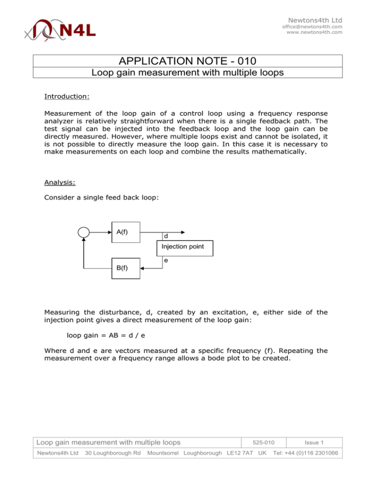
Newtons4th Ltd office@newtons4th.com www.newtons4th.com APPLICATION NOTE - 010 Loop gain measurement with multiple loops Introduction: Measurement of the loop gain of a control loop using a frequency response analyzer is relatively straightforward when there is a single feedback path. The test signal can be injected into the feedback loop and the loop gain can be directly measured. However, where multiple loops exist and cannot be isolated, it is not possible to directly measure the loop gain. In this case it is necessary to make measurements on each loop and combine the results mathematically. Analysis: Consider a single feed back loop: A(f) d Injection point e B(f) Measuring the disturbance, d, created by an excitation, e, either side of the injection point gives a direct measurement of the loop gain: loop gain = AB = d / e Where d and e are vectors measured at a specific frequency (f). Repeating the measurement over a frequency range allows a bode plot to be created. Loop gain measurement with multiple loops Newtons4th Ltd 30 Loughborough Rd 525-010 Mountsorrel Loughborough LE12 7AT UK Issue 1 Tel: +44 (0)116 2301066 Newtons4th Ltd office@newtons4th.com www.newtons4th.com Consider a control loop with 2 feedback paths: C(f) d2 Injection point 2 A(f) e3 d1 e2 Injection point 1 Injection point 3 e1 d3 B(f) D(f) The loop gain could be measured directly if it is possible to access injection point 3. However in most real control loops it is often impractical to make good measurements here either because it is inaccessible or because of the sensitivity of that part of the control circuitry. Clearly if it were possible, then the loop gain would be given by: loop gain = AB + CD = d3 / e3 Alternatively the two loops can be measured independently at injection point 1 and injection point 2, with the other loop still in circuit, and the results combined. Considering loop 1, the disturbance d1 due to excitation e1 is given by: so d1 = = d1 (1 – C.D) = d1/e1 = A [ B.e1 + C.D.d1/A ] A.B.e1 + C.D.d1 A.B.e1 A.B / (1 – C.D) Considering loop 2, the disturbance d2 due to excitation e2 is given by: so d2 = = d2 (1 – A.B) = d2/e2 = C [ D.e2 + A.B.d2/C ] C.D.e2 + A.B.d2 C.D.e2 C.D / (1 – A.B) Loop gain measurement with multiple loops Newtons4th Ltd 30 Loughborough Rd 525-010 Mountsorrel Loughborough LE12 7AT UK Issue 1 Tel: +44 (0)116 2301066 Newtons4th Ltd office@newtons4th.com www.newtons4th.com To simplify the equations, let us call the measured gain of loop 1, G1 and the measured gain of loop 2, G2; and let us call the actual gain of loop 1, L1 and the actual gain of loop 2, L2: and L1 = A.B L2 = C.D then and G1 = L1 / (1 – L2) G2 = L2 / (1 – L1) Now, G1.G2 = L1.L2 / (1 - L1)(1 - L2) and 1 – G1.G2 = (1 - L1 - L2) / (1 - L1)(1 - L2) Also, G1 + G2 = L1 / (1 – L2) + L2 / (1 – L1) = [L1.(1 – L1) + L2.(1 - L2)] / (1 - L1)(1 - L2) = [(1 – L1 – L2).(L1 + L2) + 2.L1.L2] / (1 - L1)(1 - L2) Combining these equations, gives the result: (G1 + G2 – 2.G1.G2) / (1 – G1.G2) = L1 + L2 This is the same result as the loop gain measured directly by injection point 3. Therefore: loop gain = (G1 + G2 – 2.G1.G2) / (1 – G1.G2) where G1 and G2 are the measured gains using injection points 1 and 2. Extending to 3 loops: Consider the case where there are 3 nested loops with measured gains of G1, G2, and G3. For the purposes of the analysis, consider the third loop to be a multiple loop with the combined loop gain of loop1 and loop2. Substituting in the gain equation above where G’ is the combined loop gain of G1 and G2, and G3 is the measured gain of the third loop: loop gain = (G’ + G3 – 2.G’.G3) / (1 – G’.G3) substituting for G’ G’ = (G1 + G2 – 2.G1.G2) / (1 – G1.G2) gives the combined result in terms of G1, G2, and G3: Loop gain measurement with multiple loops Newtons4th Ltd 30 Loughborough Rd 525-010 Mountsorrel Loughborough LE12 7AT UK Issue 1 Tel: +44 (0)116 2301066 Newtons4th Ltd office@newtons4th.com www.newtons4th.com (G1 + G2 – 2.G1.G2) + G3 – 2(G1 + G2 – 2.G1.G2) G3 1 – G1.G2 1 – G1.G2 loop gain = ___________________________________________ 1 - (G1 + G2 – 2.G1.G2) G3 1 – G1.G2 Simplifying the equation by cancelling the (1 – G1.G2) term throughout: loop gain = G1 + G2 – 2.G1.G2 + G3(1 – G1.G2) – 2(G1 + G2 – 2.G1.G2) G3 1 – G1G2 - (G1 + G2 – 2G1G2) G3 = G1 + G2 + G3 – 2 (G1.G2 + G1.G3 + G2.G3) +3.G1.G2.G3 1 – (G1.G2 + G1.G3 + G2.G3) + 2.G1.G2.G3 where G1, G2 and G3 are the measured gains using injection points 1, 2 and 3. Practical considerations: Recommended techniques for the measurement of a single loop within a multiple feedback control circuit are given in other N4L support documents as follows: 1. Application Note 002 – Testing Loop Stability 2. Testing loop stability – PC simulation or real measurement 3. Guide to SMPS control loop testing Loop gain measurement with multiple loops Newtons4th Ltd 30 Loughborough Rd 525-010 Mountsorrel Loughborough LE12 7AT UK Issue 1 Tel: +44 (0)116 2301066


