Automated Optimal Synthesis Of Microresonators
advertisement
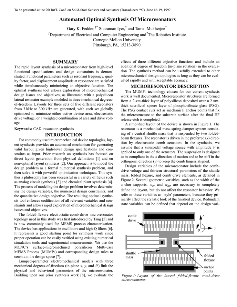
To be presented at the 9th Int’l. Conf. on Solid-State Sensors and Actuators (Transducers ‘97), June 16-19, 1997. Automated Optimal Synthesis Of Microresonators Gary K. Fedder,†* Sitaraman Iyer,† and Tamal Mukherjee† †Department of Electrical and Computer Engineering and*The Robotics Institute Carnegie Mellon University Pittsburgh, PA, 15213-3890 SUMMARY The rapid layout synthesis of a microresonator from high-level functional specifications and design constraints is demonstrated. Functional parameters such as resonant frequency, quality factor, and displacement amplitude at resonance are satisfied while simultaneously minimizing an objective function. The optimal synthesis tool allows exploration of micromechanical design issues and objectives, as illustrated with a polysilicon lateral resonator example modeled in three mechanical degreesof-freedom. Layouts for three sets of five different resonators from 3 kHz to 300 kHz are generated, with each set globally optimized to minimize either active device area, electrostatic drive voltage, or a weighted combination of area and drive voltage. Keywords: CAD, resonator, synthesis INTRODUCTION For commonly used micromechanical device topologies, layout synthesis provides an automated mechanism for generating valid layout given high-level design specifications and constraints as input. Prior research on synthesis has focused on direct layout generation from physical definitions [1] and on non-optimal layout synthesis [2]. Our approach is to model the design problem as a formal numerical synthesis problem, and then solve it with powerful optimization techniques. This synthesis philosophy has been successful in a variety of fields such as analog circuit synthesis [3] and chemical plant synthesis [4]. The process of modeling the design problem involves determining the design variables, the numerical design constraints, and the quantitative design objective. The resulting optimal synthesis tool enforces codification of all relevant variables and constraints and allows rapid exploration of micromechanical design issues and objectives. The folded-flexure electrostatic-comb-drive microresonator topology used in this study was first introduced by Tang [5] and is now commonly used for MEMS process characterization. The device has applications in oscillators and high-Q filters [6]. It represents a good starting point for synthesis work since proper operation can be easily verified using existing numerical simulation tools and experimental measurements. We use the MCNC’s surface-micromachined polysilicon Multi-user MEMS Process (MUMPs) and corresponding design rules to constrain the design space [7]. Lumped-parameter electromechanical models with three mechanical degrees-of-freedom (in-plane x, y, and θ ) link the physical and behavioral parameters of the microresonator. Building upon our prior synthesis work [8], we evaluate the effects of three different objective functions and include an additional degree of freedom (in-plane rotation) in the evaluation. The synthesis method can be usefully extended to other micromechanical design topologies as long as they can be evaluated rapidly and with acceptable accuracy. MICRORESONATOR DESCRIPTION The MUMPs technology chosen for our current synthesis work is well documented. Microresonator structures are formed from a 2 µm-thick layer of polysilicon deposited over a 2 µmthick sacrificial spacer layer of phosphosilicate glass (PSG). The PSG contact cuts act as mechanical anchor points that fix the microstructure to the substrate surface after the final HF release etch is completed. A simplified layout of the device is shown in Figure 1. The resonator is a mechanical mass-spring-damper system consisting of a central shuttle mass that is suspended by two foldedbeam flexures. The resonator is driven in the preferred (x) direction by electrostatic comb actuators. In the synthesis, we assume that a sinusoidal voltage source with amplitude V is applied to only one of the actuators. The suspension is designed to be compliant in the x direction of motion and to be stiff in the orthogonal direction (y) to keep the comb fingers aligned. Design variables of the microresonator include the combdrive voltage and thirteen structural parameters of the shuttle mass, folded flexure, and comb drive elements, as detailed in Figure 2. Several geometric variables, such as the width of the anchor supports, war and was, are necessary to completely define the layout, but do not affect the resonator behavior. We refer to these variables as ‘style’ parameters, because they primarily affect the stylistic look of the finished device. Redundant state variables can be defined that depend on the design varix comb drive θ shuttle mass y folded flexure anchor points Figure 1: Layout of the lateral folded-flexure comb-drive microresonator. This document was created with FrameMaker 4.0.4 Lb w ar w sy w sa L sa F F F Lt wb Lsy (a) F w as (b) wt g xo Lc w cy wc L cy (c) (d) Figure 2: Parameterized elements of the microresonator. (a) shuttle mass, (b) folded flexure, (c) comb drive with N movable ‘rotor’ fingers, (d) close-up view of comb fingers. ables. For example, the shuttle axle length, Lsa, is a state variable which is dependent on the truss beam length and the gap between the beam anchor and the shuttle yoke. In our formulation of the problem, this gap is a style parameter. The three rigid-body lateral translational and rotational modes (x, y, and θ) of the resonator are modeled by lumped mass-spring-damper equations of motion. The out-of-plane modes and other higher order modes are not included in the present synthesis implementation. The effect of spring mass on resonance frequency is incorporated in effective masses for each lateral mode. The maximum velocity and total kinetic energy of the spring, from which the effective mass is extracted, is approximated from static mode shapes. Viscous damping generated by the moving shuttle in air is modeled as Couette flow using the equations in [9]. Damping factors of the other lateral modes do not enter into the design constraints and are not calculated. Linear equations for the folded-flexure spring constants are found by using energy methods to find displacement for a unit load on the end of the spring [10]. Axial compression and extension are included in expressions for ky and kθ. General analytic equations for the lateral comb-drive force, Fx, as a function of wc, g, structure thickness, and sacrificial spacer thickness are derived in [11]. If the comb fingers are not perfectly centered, a y-directed electrostatic force is also present. Assuming a small perturbation y, the destabilizing force, Fe,y, is proportional to displacement, such that Fe,y = ke,y y, where ke,y is an ‘electrical spring constant.’ LAYOUT SYNTHESIS Design Constraints Constraints on the design specifications are assigned realistic values for synthesizing a valid resonator for use as a characterization structure. Alternative constraint values can be readily assigned in the implementation. An essential specification is resonant frequency of the lowest (preferred) mode, ωx = 2π fx = k x ⁄ m x , where kx is the spring Lsy+∆ outer beams in compression inner beams in tension Figure 3: Schematic of the effect of compressive residual stress on the folded-flexure suspension. constant and mx is the effective mass. A valid layout must have a resonant frequency within 10% of the desired value. Resonant frequencies of the other two lateral modes, fy and fθ, must be at least ten times greater than fx to decouple the modes adequately. For stability, the restoring force of the spring in the y direction must be greater than the destabilizing electrostatic force from the comb drive (i.e., k e, y < k y ). A similar stability constraint must hold for the rotational mode. Assuming the system is underdamped, the displacement amplitude at resonance is x max = QF x ⁄ k x , where F x ∝ NV 2 is the comb-drive force, Q = 2 m x k ⁄ B x is the quality facx tor, and Bx is the damping coefficient. We have constrained xmax = 3 µm ± 10% at a drive voltage of V < 100 V to enable easy visual confirmation of resonance, and Q ≥ 5 to ensure underdamped resonant operation. Beams in the folded-flexure are free to expand outward to relieve residual axial stress. However, as shown in Figure 3, the central shuttle also expands an amount ∆ due to residual stress, creating additional axial stress in the outer beams and tension in the inner beams. A first-order value of the critical buckling length, Lcr, for the folded-flexure is given by the Euler column formula, L cr = π t 2 Lb ⁄ 3 ∆ , where 2Lb < Lcr to ensure no buckling. The layout is constrained by the MUMPs design rules. Technology-driven design rules set minimum beam widths and minimum spaces between structures. We have constrained maximum element lengths to 300 µm to avoid problems with undesirable curling due to stress gradients in the structural film and possible sticking and breakage during the wet release etch. Synthesis Algorithm Synthesis of the microresonator will result in one of two possible outcomes. Several designs may satisfy the above constraints, or no designs may meet the constraints (null design space). Our synthesis approach is to select the design that minimizes an objective function and therefore may be considered optimal. The synthesized result depends very strongly on the choice of objective function. For the microresonator, we have chosen three objective functions to evaluate: total active area, amplitude of the comb-drive voltage, and the sum of area and voltage normalized to the maximum possible area and voltage. In our approach, the synthesis problem is mapped onto a constrained optimization formulation that is solved in an unconstrained fashion [12]. As a result, the goal becomes minimization of a scalar cost function. Evaluating the cost function involves firing the lumped-element macromodels to determine the extent to which the design constraints are met, for the current values of the design variables. This cost function has multiple minima due to the complex nonlinear characteristics of the individual equations in the lumped-element macromodel. Currently, a gridded numerical optimization algorithm efficiently solves for the global minimum of the objective function. Our next-generation tool will use simulated annealing [13] as the optimization engine to drive the search for the minimum; it provides robustness and the potential for global optimization in the face of many local minima. Because annealing incorporates controlled hill-climbing, it can escape local minima and is essentially starting-point independent. RESULTS AND DISCUSSION Three sets of resonators synthesized from specifications are shown in Figure 4. Each set is optimized for a different objective function. For visualization of the synthesis results, we used the Consolidated Micromechanical Element Library (CaMEL) parameterized module generation software [1] which provides CIF output when given resonator layout parameters. The CaMEL generators automatically place holes in the large plates that are over 30 µm in size. Feedback from many synthesis iterations directed our efforts to codify the design variables and constraints necessary to produce synthesized designs that followed manual design convention and common sense. The layout visualization was instrumental in debugging the equations. In many cases, a quick inspection of a synthesized layout was all that was needed to determine errant or missing equations. All of the optimal designs had minimum widths of beams and trusses, and minimum comb finger dimensions. The generated layouts for each objective function converge at the edges of the design space (1.5 kHz to 600 kHz), as can be seen by comparing the highest and lowest frequency resonators in Figure 4 (a) and (b). Single-finger comb-drive resonators, shown in Figure 4 (c), are generated to minimize active area. Convergence of the minimum area resonators with the other synthesized devices does occur, but it happens extremely close to the edges of the design space. Values of selected design variables and behavioral parameters for the mixed area-voltage objective are given in Table 1. The analytic expressions for spring constants and resonant frequencies were verified with finite-element simulation (ABAQUS) of the resonators using 2D 8-node plane stress elements to model the entire structure. Analytic spring constants in x are within 5%, but much more accurate at low frequencies. Spring constants and resonant frequencies in y and θ have errors exceeding 30%. This is due to lateral bending in the central shuttle axle, which causes the system stiffness to be significantly reduced. In the future, we will include this effect in the lumped models and introduce a stiffness constraint on the shuttle axle width, wsa. Resonators have also been fabricated in MUMPs, however quantitative results are not yet available. As expected, the resonators become smaller with increasing values of resonant frequency. Smaller devices have less mass, and smaller flexures are stiffer. Both effects increase the resonant frequency. Parameters directly relevant to the high-frequency limit are plotted in Figure 5 (a). At around 600 kHz, the voltage limit is reached and N must be increased to provide adequate electrostatic force to achieve the 2.7 µm minimum displacement. Higher frequency resonators cannot be synthesized because the necessary increase in comb fingers generates a more massive device, which drives the resonant frequency down. The simulated values for fθ /fx listed in Table 1 violate the constraint for the 100 kHz and 300 kHz resonators. Therefore, it is likely that the actual high-frequency limit for designs is due to the modal decoupling and not to the drive voltage. (b) 3 kHz (a) (c) 3 kHz not shown 30 kHz 10 kHz 3 kHz 10 kHz 10 kHz 30 kHz 100 kHz 30 kHz 300 kHz 100 kHz 300 kHz 100 kHz 300 kHz Figure 4: Layout synthesis results for three different objective functions. (a) Minimize normalized sum of area and voltage. (b) Minimize voltage. (c) Minimize active area. Table 1: Selected behavioral and physical parameters for the five synthesized resonators with minimized area and voltage fx Spec (± 10%) 3 kHz 10 30 100 300 fx [kHz] 3.30 9.05 27.0 90.1 270. fx, sim [kHz] 3.37 9.83 29.3 97.6 284. fθ [kHz] 35.2 222. 287. 899. 2700. fθ, sim [kHz] 25.8 165. 257. 378. 781. kx [N/m] 0.194 0.194 1.47 15.0 91.1 kx sim [N/m] 0.195 0.195 1.46 14.8 86.9 mx [pg] 453. 60.1 51.2 46.8 31.6 Qx 9.09 16.6 49.0 152. 388. Lb [µm] 300. 300. 154. 67.5 30.9 82 44 39 36 21 8.42 8.51 14.5 27.3 55.1 N V [V] Low frequency resonators are limited both by the upper bounds imposed on geometry and by excessive damping as illustrated in Figure 5 (b). The maximum beam length of 300 µm set a lower limit on spring constant of around 0.2 N/m. The shuttle mass can still be increased by making the comb yoke width, wcy, larger. However, quality factor decreases with increasing plate mass, due to the air drag over the larger plate area. The minimum acceptable quality factor of 5 is reached before the physical constraint on plate size is violated. Note that although N is more than doubled from the 10 kHz to 3 kHz device, the Q is reduced by about 1/2. Therefore, the applied voltage stays nearly constant for these devices. CONCLUSIONS Synthesis algorithms have been successfully applied to automatic layout of surface-micromachined resonators. A prerequisite for synthesis is a set of lumped-parameter models that adequately link device behavior with physical design variables. One important benefit of creating synthesis tools is that it forces the CAD developer to codify every design variable and design constraint which then becomes reusable information. Optimal synthesis enables exploration of the entire design space given specific user-specified constraints, as has been shown with the resonator example. Once a structured design methodology is established for surface-micromachined MEMS, the synthesis techniques may be extended in the future to general parameterized designs. ACKNOWLEDGEMENT The authors thank Karen Markus and Ramaswamy Mahadevan of MCNC for use of the CaMEL tool. The research effort was sponsored by DARPA/ETO F30602-96-2-0304, and in part by G. K. Fedder’s NSF CAREER Award MIP-9625471. REFERENCES [1] CaMEL Web Page, http://www.mcnc.org/camel.org, MCNC MEMS Technology Applications Center, 3021 Cornwallis Road, Research Triangle Park, NC 27709. 100 100 maximum V N V 80 60 10 40 20 min. fθ /fx 0 1 kHz fθ /fx 10 kHz 100 kHz (a) V, N, and fθ /fx vs. fx 1 1 MHz 400 1000 Lb [µm] 300 Q maximum Lb 100 200 minimum Q 100 10 wcy [µm] 0 1 kHz 10 kHz 100 kHz (b) Lb, wcy, and Q vs. fx 1 1 MHz Figure 5: Selected design parameters for the synthesized resonators with minimized area and voltage. (a) Parameters restricting the high-frequency design space. (b) Parameters restricting the low-frequency design space. [2] [3] [4] [5] [6] [7] [8] [9] [10] [11] [12] [13] N.R. Lo, E. C. Berg, J.N.Simon, H. Lee, M. Tachiki, and K.S.J.Pister, Proc. ISCAS, Atlanta, GA, 1996. T. Mukherjee, L.R. Carley, and R.A. Rutenbar, Proc. ACM/IEEE ICCAD, pp. 586-593, 1994. I. E. Grossmann and D. A. Straub, Proc. COPE-91, pp 49-59, 1991. W. C. Tang, T.-C. H. Nguyen, M. W. Judy, and R. T. Howe, Sensors and Actuators A, vol.21, no.1-3, pp. 32831, 1990. C. T.-C. Nguyen and R. T. Howe, Proc. IEEE Int. Electron Devices Meeting, San Francisco, CA, pp. 343, 1994. D. A. Koester, R. Mahadevan, K. W. Markus, MUMPs Introduction and Design Rules, MCNC MEMS Technology Applications Center, 3021 Cornwallis Road, Research Triangle Park, NC 27709, rev. 3, Oct. 1994. G.K. Fedder and T. Mukherjee, Proc. 5th ACM/SIGDA Physical Design Workshop, Reston, VA, pp.53-60, 1996. X. Zhang and W. C. Tang, Sensors and Materials, v. 7, no. 6, pp.415-430, 1995. J. M. Gere and S. P. Timoshenko, Mechanics of Materials, 4th ed., Boston: PWS Publishing Co., 1997. W. A. Johnson and L. K. Warne, J. of Microelectromechanical Systems, v.4, no.1, pp.49-59, 1995. E. S. Ochotta, R. A. Rutenbar, and L. R. Carley, Proc. 31st ACM/IEEE DAC, pp. 24-30, 1994. S. Kirkpatrick, C. D. Gelatt, and M. P. Vecchi, Science, vol. 220, no. 4598, 1983.


