Bodypart Localization for Pressure Ulcer Prevention Jason J. Liu , Ming-Chun Huang
advertisement
Bodypart Localization for Pressure Ulcer Prevention
Jason J. Liu1 , Ming-Chun Huang1 , Wenyao Xu2 , Majid Sarrafzadeh1
Abstract— Pressure ulcers, commonly called bedsores, are
defined as injuries to the skin and underlying tissue resulting
from prolonged pressure usually on bony areas of the body, such
as heels and hips. In order to alleviate pressure accumulation
at high-risk regions, the current practice in clinics requires
caregivers to reposition their patients every two hours. This
relies on the engagement of nursing services and places large
burdens on the caregivers. In this study, a bedsore monitoring
method using Pictorial Structure models is introduced to localize pressure distributions of the body. A pilot study including
12 subjects reveals that the proposed method enables reliable
localization of bodyparts with 89.8% accuracy in common lying
postures.
I. I NTRODUCTION AND R ELATED W ORK
One of the main problems for post-surgical patients and
elderly patients is formation of pressure ulcers [1]. Pressure
ulcers, or bedsores, are localized injury to body tissue,
usually near the bone, resulting from lack of movement and
obstructed blood circulation. In hospital settings, caregivers
need to be attentive to subjects that are more susceptible
to this condition, and take action to relieve pressure on the
highly sensitive locations by changing their sleep postures.
Current best practices in nursing involve turning patients
every several hours [2]. Higher quality mattresses or softer
overlays that attempt to distribute pressure more evenly
have been used, while dynamic surfaces such as alternating
pressure overlays that employ circulating air or liquid have
shown to be effective [3].
Given that pressure ulcers can develop very quickly, the
autonomous monitoring of high risk areas is a realistic goal.
The goal of any medical system that prevents the formation
of pressure ulcers requires the analysis of sleeping postures,
as well as notifications of susceptible and impending pressure points on the patient’s body. It is well known which
bodyparts are most prone to pressure ulcers: sacrum, heels,
trochanter (hips), and elbows [4]. Therefore, there is indeed
a need to automatically locate these bodyparts, measure the
accumulated pressure, and notify hospital staff of impending
issues.
With recent advances in technology, pressure sensors are
being increasingly deployed in various devices for measuring
pressure on the body. Current commercial systems in the
form of sheets are undergoing greater use [5], [6]. These
sensors have a variety of resolutions and are able to accurately measure pressure distributions under the body. Other
research projects are more focused on developing low-cost
1 Department
of Computer Science, University of California, Los Angeles
of Computer Science and Engineering, the State University
of New York (SUNY) at Buffalo, New York
E-mail: {jasonliu,mingchuh,majid}@cs.ucla.edu, wenyaoxu@buffalo.edu
2 Department
978-1-4244-7929-0/14/$26.00 ©2014 IEEE
disposable sheets compared to existing commercial systems.
A capacitive pressure sensor array was designed by Yip et
al. with an estimated low cost of $50/m2 [7]. Our previous
work involved designing an eTextile bedsheet that employed
the piezoelectric characteristics of such materials [8].
Using a commerical pressure sensitive mat, Farshbaf et
al. located bodyparts with a reported average accuracy of
85.7% [9]. Their method involved extracting the body boundary through filtering, dilation, and edge detection. Then, with
Constrained Delaunay Triangulation, they were able to prune
a skeletal graph. Finally, by applying Dynamic Time Warping
to the skeleton, the nodes and leaves can be matched to a predefined bodypart template of the human body. In conjunction
with Siemens magnetic resonance imaging (MRI), Grimm et
al. used constrained articulated ellipsoid modelling of the
body to minimize the error between the pressure image and
generated images [10]. In this case, bodypart localization
helped to fine tune specific scans of the patient. To our
knowledge, these works are the only published prior art in
bodypart localization using pressure sensors with the purpose
of pressure ulcer prevention.
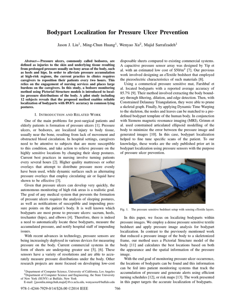
Fig. 1. The pressure sensitive bedsheet setup with sensing eTextile layers.
In this paper, we focus on localizing bodyparts within
pressure images. We employ a dense pressure sensitive textile
bedsheet and apply pressure image analysis for bodypart
localization. In contrast to the previously mentioned work
that reduced a pressure image of the body to a skeletonized
frame, our method uses a Pictorial Structure model of the
body [11] and calculates the best locations based on both
the appearance and the spatial information of the pressure
image.
With the end goal of monitoring pressure ulcer occurrence,
the locations of bodyparts can be found and this information
can be fed into patient monitoring systems that track the
accumulation of pressure and generate alerts using efficient
turning schedules [12], or risk maps [13]. The work presented
in this paper targets the accurate localization of bodyparts.
766
II. P RESSURE S ENSOR
Figure 1 shows the prototype of the bedsheet system. The
sensor system consists of three components: a 64 × 128
pressure sensor array, a data sampling unit, and a tablet
for data analysis and storage. The sensor array is based
on eTextile material which is fiber-based yarn coated with
piezoelectric polymer [14]. The initial resistance of the
eTextile material is high. As external force is applied to
the surfaces of the material, the eTextile fibers are squeezed
together and, due to its pressure sensitive characteristics, the
electrical resistance decreases in that region.
The bedsheet has a three-layer sandwiched structure. The
top layer is regular fabric that is coated with 64 parallel
conductive lines. The middle layer is the eTextile material
and the bottom layer has 128 conductive lines arranged
perpendicular to the top 64 lines. At each intersection of
conductive lines, the structure forms a pressure sensitive
resistor. There are effectively 8192 pressure sensors in total.
III. M ETHOD
This method is based on the pictorial structures model,
proposed by Fischler and Elschlager [11], for identifying
structured objects in images. Felzenszwalb and Huttenlocher
improved the matching efficiency of the parts based algorithm using distance transforms within dynamic programming [15]. The original formulation of finding bodyparts is
described here.
Each part of the human body can be represented as a vertex
in a tree. For instance, the head, shoulders, hands and feet
are nodes in a graph connected by edges. Given an image I,
we define a mismatch cost mj (I, lj ) as a measure of how
much the image I matches a bodypart j at the location lj =
(xj , yj , θj ) where xj , yj are the co-ordinates of the center
of the bodypart model with rotation angle θj . A low value
of mismatch means the bodypart is well recognized at that
location.
In addition to the cost for how well the appearance of
each bodypart matches its template, there is a cost for the
relationship between bodypart locations. For bodyparts i and
j, a deformation cost dij (li , lj ) gives a measure of how
far the bodyparts deviate from their expected respective
locations. For instance, the hip and shoulders are known
to be separated by the spine length. So for a given set
of bodypart templates and connections between them, the
best configuration of bodyparts L = (l1 , ..., ln ) in an image
minimizes the total cost of mismatch for all parts and
deformation between all pairs of parts:
be calculated as a function of its parent location li . So the
best leaf vertex location is a function of parent location:
!
Bj (li ) = arg min mj (I, lj ) + dij (li , lj ) .
lj
(2)
For a non-leaf, non-root vertex, its best location ˆlj as a
function of its parent location li is given by
Bj (li ) = arg min mj (I, lj ) + dij (li , lj ) +
lj
X
Bc (lj ) ,
Ch(j)
(3)
where Ch(j) means children vertices of j and Bc (lj ) are the
costs of the best locations of the children of j. This is already
calculated and memoized via the dynamic programming
methodology.
Then for the root vertex (no parent), its best location is
X
ˆlj = arg min mj (I, lj ) +
Bc (lj ) ,
(4)
lj
Ch(j)
where Bc (lj ) is known for each of the children of j.
This formulation (Equations 2 to 4) reduces the number
of computations from exponential to polynomial while still
producing the globally optimal solution.
To compute the mismatch cost mj (I, lj ) for each bodypart, we select a representative template and, in this paper,
the bodyparts are simply represented as rectangular boxes
surrounded by a border due to ease of calculation (Figure 2).
The size of template is proportional to the height of the
subject. To account for different pressure images due to
varying weights of the subjects, the image I is binarized at
different thresholds. A convolution operation of this kernel
with the binary images efficiently gives the mismatch cost at
all locations. This computes how many pixels do not match
inside the inner box and within the border. Then, mismatch
cost is the smallest cost across all threshold levels for each
location.
-1 -1 -1 -1 -1 -1 -1 -1 -1 -1 -1 -1 -1 -1 -1 -1 -1 -1
-1 -1 -1 -1 -1 -1 -1 -1 -1 -1 -1 -1 -1 -1 -1 -1 -1 -1
-1 -1
1
1
1
1
1
1
1
1
1
1
1
1
1
1
-1 -1
-1 -1
1
1
1
1
1
1
1
1
1
1
1
1
1
1
-1 -1
-1 -1
1
1
1
1
1
1
1
1
1
1
1
1
1
1
-1 -1
-1 -1
1
1
1
1
1
1
1
1
1
1
1
1
1
1
-1 -1
-1 -1
1
1
1
1
1
1
1
1
1
1
1
1
1
1
-1 -1
-1 -1
1
1
1
1
1
1
1
1
1
1
1
1
1
1
-1 -1
-1 -1 -1 -1 -1 -1 -1 -1 -1 -1 -1 -1 -1 -1 -1 -1 -1 -1
-1 -1 -1 -1 -1 -1 -1 -1 -1 -1 -1 -1 -1 -1 -1 -1 -1 -1
arg min
L
X
allparts
mj (I, lj ) +
X
dij (li , lj ) .
(1)
allpairs
This formulation takes exponential time in the number
of bodyparts n, however with the tree representation of
bodyparts, this can be solved more efficiently as a chain of
computations using dynamic programming as follows. For
any leaf vertex (i.e. has no children), its best location ˆlj can
Fig. 2. Template for bodypart mismatch cost. The mismatch cost of the
bodypart model is the sum of mismatched pixels within the inner rectangle
and matching pixels in the border region.
To compute the deformation cost dij (li , lj ) between bodyparts, we define this cost to have the form
767
dij (li , lj ) = ||Tij (li ) − Tji (lj )||.
(5)
This is a simple distance metric between locations transformed to a common space. The transforms can be translations, rotations, and scaling, hence they are invertible (See
Fig. 3). The effect of the transforms is to specify the expected
relations between the locations, i.e. if two bodyparts have
no deformation cost and are correctly positioned, then the
transformed locations will coincide. The pairwise distance
metric takes quadratic time in the number of locations. For
every location of the parent, we want to compute the distance
to each location of the child. On the surface, quadratic time
may seem satisfactory but this can be improved to linear time
through the use of distance transforms [16]. In fact, every
pairwise distance between li and lj need not be computed.
From Equation 2, only the smallest sum of deformation cost
and mismatch cost is needed at each location of li .
children. The values of D[x, y, θ] can be updated according
to
D[x, y, θ] = min(D[x, y, θ],
D[x − 1, y, θ] + kx ,
D[x, y − 1, θ] + ky ,
D[x, y, θ − 1] + kθ ),
(9)
where kx , ky , kθ are constants that account for different pixel
scales. This is executed in sequence starting from array point
[1,1,1] linearly through the array which is followed by a
second sweep in the reverse direction.
li=(xi,yi,θi)
z =Tij(li)
w=Tji(lj)
lj=(xj,yj,θj)
Fig. 3.
Example transformation of bodypart models
The generalized form of a distance transform given a
function f is
!
D(z) = min ||z − w|| + f (w) ,
w
(6)
where z and w are locations in a grid. This formulation states
that, for every location z, it finds the closest location w with
the smallest value for f (w).
In Equation 6, we can map z to a translated location for
li , i.e. z = Tij (li ). w maps to a translated location for lj ,
i.e. w = Tji (lj ). f (w) is a function that maps to f (w) =
mj (I, Tji 1 (lj )). So now Equations 2 and 3 become
Bj (li ) = D(Tij (li )).
(7)
Now the final discussion describes how to speed up the
calculation of Equation 7. For the leaf nodes, we initialize
an array D[x, y, θ] with the values of mj (I, Tji 1 (Tji (lj )))
which is just the mismatch cost of the child but translated to
a new location in the same space as the parent. For non-leaf
nodes, we initialize the array D[x, y, θ] with the values of
mj (I, Tji 1 (Tij (li ))) +
X
Bc (Tji 1 (Tij (li ))),
(8)
Ch(j)
which is the mismatch cost of the child (translated to a new
location in the same space as the parent) plus the cost of the
Fig. 4. Sample image results for bodypart localization in the right lateral,
supine, and left lateral postures.
IV. E XPERIMENTAL R ESULTS
A. Experimental Setup
We run a pilot study to evaluate the performance of the
system for localization of bodyparts. There are 12 subjects
in the experiment with 9 male and 3 female subjects. The
weights of the subjects range from 50kg to 85kg, and height
between 155cm and 188cm. For the sake of consistency, the
bedsheet system is also deployed on a standard twin-size coil
spring mattress during the experiments.
In the data collection, 40 samples were recorded for each
of the 3 postures (supine, left and right) for each subject. At
fixed intervals, the pressure image of the subject’s posture
was recorded while the subject maintained a comfortable
sleeping position. Variations in body, arm and leg positions
were allowed and the system is tested on a range of positions that fall within the 3 defined postures. The following
experiments were tested against hand labelled ground truth
from direct overhead camera recordings.
768
TABLE II
AVERAGE P RESSURE AT H IGH R ISK R EGIONS FOR A S UBJECT
B. Experimental Results
Once each of the bodypart models is located, fine tuning of
the locations of the high pressure points proceeds by finding
the center of mass within the bodypart model. For the heels
and elbow, the center of mass is restricted to the lower half
of the bodypart model.
Figure 4 shows a sample of bodypart localization results in
right lateral, supine, and left lateral postures. Lateral postures
are defined by 4 bodypart models and supine posture is
defined by 8 bodyparts models. Table I summarizes the
accuracy of bodypart localization for the 3 postures compared against prior work by Farshbaf et al. [9] and Grimm
et al. [10]. We use the same metrics as described in the
prior work, where error is measured by Euclidean distance
in inches between the tested and ground truth locations, and
accuracy is calculated as the percentage of bodyparts that
have error of less than 1 inch. In these experiments, the
elbow resulted in the lowest localization accuracy. This can
be explained by the relative weakness in pressure compared
to the high pressure of the shoulder.
TABLE I
ACCURACY OF BODYPART LOCALIZATION
Accuracy
Error
Accuracy†
Error‡
Farshbaf
Grimm
(%)
(inch)
[9]
[10]
Supine
Shoulder
93.3%
1.7” *
92.4%
1.2”
Left Elbow
86.7%
87.1%
1.6”
Right Elbow
80.0%
86.2%
1.7”
Sacrum
93.3%
1.7”
94.7%
0.9”
Left Heel
80.0%
93.1%
1.0”
Right Heel
80.0%
93.7%
1.0”
Left
Shoulder
86.7%
2.9”
94.5%
0.9”
Elbow
76.7%
82.1%
2.2”
Hip
93.3%
2.0”
91.9%
1.3”
Knee
3.3”
90.0%
1.8”
Right
Shoulder
90.0%
2.3”
92.1%
1.2”
Elbow
96.7%
84.5%
2.0”
Hip
90.0%
2.0”
92.2%
1.2”
Knee
3.3”
85.2%
2.0”
Average
85.7%
2.7”
89.8%
1.4”
†Accuracy is percentage of bodyparts within 1 inch of groundtruth.
‡Error is Euclidean distance from groundtruth location.
*Grimm et al. reported neck location instead.
Posture
Bodypart
Table II shows the average pressure of a sample subject.
For this method of bodypart localization, the total accumulation of pressure can be recorded to facilitate pressure ulcer
monitoring and prevention.
V. C ONCLUSION
This work presents a method to localize bodyparts using
a pressure sensitive bedsheet. The purpose of such a system
is to enable caregivers the ability to automatically identify
where patients are at risk of developing pressure ulcers. In
our experiments, we showed an overall localization accuracy
of 89.8% for high risk regions such as the hip, heels, and
shoulders. Future work also involves the ability to monitor
accumulated pressure over continuous periods.
Bodypart (posture)
average pressure* (x 10−3 )
Sacrum (supine)
2.09 ± 0.13
Shoulder (lateral)
2.01 ± 0.13
Hip (lateral)
1.92 ± 0.11
Heel (supine)
1.52 ± 0.12
Elbow (supine)
1.43 ± 0.10
Shoulder (supine)
0.80 ± 0.09
Non risk areas
< 0.2
*Pressure values given are the pixel values
when sum of pixels is normalized to 1.
ACKNOWLEDGMENT
The authors would like to thank Medisens Wireless Inc. for
their contributions in discussion and building the hardware.
R EFERENCES
[1] T. Perneger, C. Heliot, A.-C. Rae, and J.-M. Gaspoz, “Hospitalacquired pressure ulcers: Risk factors and use of preventive devices,”
Archives Internal Med., vol. 158, no. 17, pp. 1940–45, 1998.
[2] J. K. Stechmiller, L. Cowan, J. D. Whitney, L. Phillips, R. Aslam,
A. Barbul, F. Gottrup, L. Gould, M. C. Robson, G. Rodeheaver et al.,
“Guidelines for the prevention of pressure ulcers,” Wound Repair and
Regeneration, vol. 16, no. 2, pp. 151–168, 2008.
[3] C. Chai and D. Bader, “The physiological response of skin tissues to
alternating support pressures in able-bodied subjects,” Journal of the
Mechanical Behavior of Biomedical Materials, vol. 28, pp. 427–435,
2013.
[4] A. Thoroddsen, “Pressure sore prevalence: a national survey,” Journal
of Clinical Nursing, vol. 8, no. 2, pp. 170–179, 1999.
[5] Xsensor, http://www.xsensor.com.
[6] VistaMedical, http://www.pressuremapping.com.
[7] M. Yip, D. He, E. Winokur, A. G. Balderrama, R. Sheridan, and H. Ma,
“A flexible pressure monitoring system for pressure ulcer prevention,”
in International Conference of IEEE Engineering in Medicine and
Biology Society, EMBC. IEEE, 2009, pp. 1212–5.
[8] J. J. Liu, W. Xu, M.-C. Huang, N. Alshurafa, M. Sarrafzadeh, N. Raut,
and B. Yadegar, “A dense pressure sensitive bedsheet design for
unobtrusive sleep posture monitoring,” in Pervasive Computing and
Communications (PerCom), International Conference. IEEE, 2013,
pp. 207–215.
[9] M. Farshbaf, R. Yousefi, M. Baran Pouyan, S. Ostadabbas,
M. Nourani, and M. Pompeo, “Detecting high-risk regions for pressure
ulcer risk assessment,” in International Conference on Bioinformatics
and Biomedicine. IEEE, 2013.
[10] R. Grimm, J. Sukkau, J. Hornegger, and G. Greiner, “Automatic
patient pose estimation using pressure sensing mattresses,” in Bildverarbeitung fur die Medizin 2011, ser. Informatik aktuell, 2011.
[11] M. A. Fischler and R. A. Elschlager, “The representation and matching
of pictorial structures,” IEEE Transactions on Computers, vol. 22,
no. 1, pp. 67–92, 1973.
[12] S. Ostadabbas, R. Yousefi, M. Faezipour, M. Nourani, and M. Pompeo,
“Pressure ulcer prevention: An efficient turning schedule for bedbound patients,” in Life Science Systems and Applications Workshop
(LiSSA), 2011 IEEE/NIH. IEEE, 2011, pp. 159–162.
[13] I. Main, R. Miller, T. Russel, and M. Ousdahl, “Risk
modeling for pressure ulcer formation,” Aug. 4 2011,
wO Patent App. PCT/CA2011/000,098. [Online]. Available:
https://www.google.com/patents/WO2011091517A1?cl=en
[14] W. Xu, Z. Li, M.-C. Huang, N. Amini, and M. Sarrafzadeh, “eCushion:
An eTextile Device for Sitting Posture Monitoring,” in Body Sensor
Networks (BSN), May 2011, pp. 194–199.
[15] P. F. Felzenszwalb and D. P. Huttenlocher, “Pictorial structures for
object recognition,” International Journal of Computer Vision, vol. 61,
no. 1, pp. 55–79, 2005.
[16] G. Borgefors, “Distance transformations in digital images,” Computer
vision, graphics, and image processing, vol. 34, no. 3, pp. 344–71,
1986.
769
