analog instruments - ELECTRONICS AND INSTRUMENTATION
advertisement

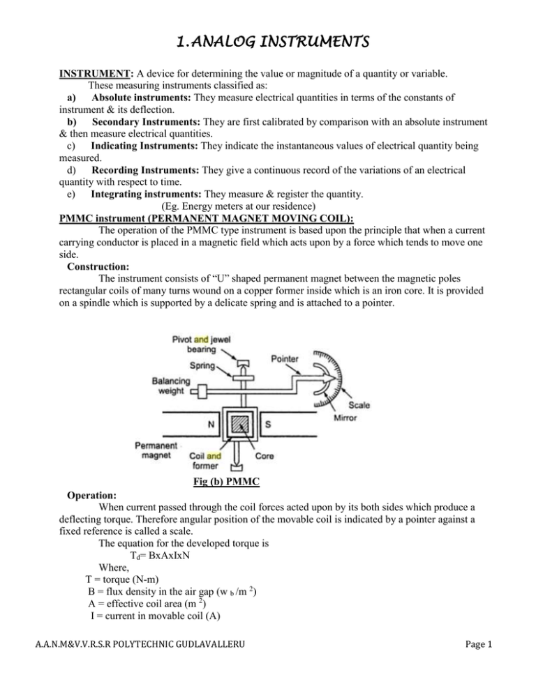
1. ANALOG INSTRUMENTS INSTRUMENT: A device for determining the value or magnitude of a quantity or variable. These measuring instruments classified as: a) Absolute instruments: They measure electrical quantities in terms of the constants of instrument & its deflection. b) Secondary Instruments: They are first calibrated by comparison with an absolute instrument & then measure electrical quantities. c) Indicating Instruments: They indicate the instantaneous values of electrical quantity being measured. d) Recording Instruments: They give a continuous record of the variations of an electrical quantity with respect to time. e) Integrating instruments: They measure & register the quantity. (Eg. Energy meters at our residence) PMMC instrument (PERMANENT MAGNET MOVING COIL): The operation of the PMMC type instrument is based upon the principle that when a current carrying conductor is placed in a magnetic field which acts upon by a force which tends to move one side. Construction: The instrument consists of “U” shaped permanent magnet between the magnetic poles rectangular coils of many turns wound on a copper former inside which is an iron core. It is provided on a spindle which is supported by a delicate spring and is attached to a pointer. Fig (b) PMMC Operation: When current passed through the coil forces acted upon by its both sides which produce a deflecting torque. Therefore angular position of the movable coil is indicated by a pointer against a fixed reference is called a scale. The equation for the developed torque is Td= BxAxIxN Where, T = torque (N-m) B = flux density in the air gap (w b /m 2) A = effective coil area (m 2) I = current in movable coil (A) A.A.N.M&V.V.R.S.R POLYTECHNIC GUDLAVALLERU Page 1 1. ANALOG INSTRUMENTS N = number of turns in the coil If B&A are constant the deflecting torque is directly proportional to the applied current. The deflecting torque is balanced by the opposing control-spring torque (Tc) Tc α deflection, θ Tc = K. θ K-Spring constant Therefore Tc= Td i.e.., θ=I Advantages: 1. They have low power consumption. 2. They have no hysteresis 3. Their scales are uniform 4. They can be designed to extend over an arc of 270 degrees. 5. They posses more torque. Disadvantages: 1. Errors are due to ageing of control spring and permanent magnet. 2. They cannot be used for A.C measurements. 3. They are costlier than moving iron instruments. DC Ammeter: Fig (b) Basic DC ammeter ciruit The basic movement of a DC ammeter is a PMMC galvanometer. Since, the coil winding of a basic movement is small and light. So, it measures very small currents. For large currents, It is necessary to bypass a major part of the current through a resistance called “SHUNT (Rs)” The resistance of a shunt can be calculated by applying conventional circuit analysis in fig (a) Rm-> Meter resistance Rsh-> Shunt resistance Im-> Full scale deflection current of the movement Ish-> Shunt current I-> Full scale current The shunt resistance resistances voltage is same as the movement voltage. Therefore, A.A.N.M&V.V.R.S.R POLYTECHNIC GUDLAVALLERU Page 2 1. ANALOG INSTRUMENTS Extending the range of DC ammeter: Fig (C) Extending the range of DC ammeter The current range can be extended by a no. of shunts selected by a range switch S such a meter is called “MULTIRANGE AMMETER.” The circuit has four shunts R1, R2, R3 & R4 which can be placed in parallel with the movement to give four different current ranges I1, I2, I3 & I4. A.A.N.M&V.V.R.S.R POLYTECHNIC GUDLAVALLERU Page 3 1. ANALOG INSTRUMENTS DC VOLTMETER: A basic D’Arsonval movement can be converted into a DC voltemeter by adding a series resistor known as “MULTIPLIER” Fig (D) DC voltmeter The function of the multiplier is to limit the current through the movement. So that the current does not exceed the full scale deflection value. A DC voltmeter is always connected across the voltage to be measured with proper polarity. The value of the multiplier required to extend the voltage range is calculated from fig (d). 𝑉 − 𝐼𝑚. 𝑅𝑚 𝑅𝑠 = 𝐼𝑚 EXTENDING THE RANGE OF VOLTMETER: The addition of no. of multipliers together with a range switch provides the instrument with a no. of voltage ranges. Above Fig shows a multirange voltmeter using a Four position switch and four multipliers for the voltage ranges V1, V2, V3 & V4. The value of the multiplier can be calculated by using the formula 𝑅𝑠 = A.A.N.M&V.V.R.S.R POLYTECHNIC GUDLAVALLERU 𝑉 − 𝐼𝑚. 𝑅𝑚 𝐼𝑚 Page 4 1. ANALOG INSTRUMENTS RECTIFIER TYPE VOLTMETER: Rectifier type instruments generally use a PMMC movement along with a rectifier arrangement gives an AC voltmeter consists of a multiplier bridge rectifier and a PMMC movement. Full-Wave rectifier voltmeter: An AC voltmeter circuit consisting of a multiplier, bridge rectifier and a PMMC movement is shown in figure. The bridge rectifier produces a pulsating DC. But, the meter will indicates a steady deflection proportional to the average value of the current. Since, Alternating currents and voltages are usually expressed in RMS values. The meter scale is calibrated in terms of the RMS value of a sinusoidal waveform. The Full wave bridge rectifier circuit in fig passes the positive half cycles of the sinusoidal input waveform and inverts the negative half cycles. The resulting current waveform is a series of the +ve half cycles. The meter has low sensitivity because of high resistance of diodes. Half wave rectifier voltmeter: Half wave rectification is employed in the AC voltmeter circuit shown in figure. Rsh shunting the meter A.A.N.M&V.V.R.S.R POLYTECHNIC GUDLAVALLERU Page 5 1. ANALOG INSTRUMENTS Diode D1 conducts during the positive half cycle and causes the meter to deflect according to the average value of positive half cycle. The meter movement is shunted by a resistor Rsh in order to draw more current. Diode D2 conducts during the negative half cycle and the current through the measuring circuit which is in opposite direction. Rectifier type Ammeter: The basic arrangement of rectifier type ammeter as shown in fig for AC current measurement. Like a DC ammeter an AC ammeter must have a low resistance. The low resistance means that the voltage drops across the ammeter must be very small. It is in the range of 100mV. However the voltage drop across the diode is 0.3 to 0.7 volts. When a bridge rectifier circuit is used the total diode voltage drop is 0.6 to 1.4V. Therefore, a rectifier instrument is not suitable for an AC ammeter. The use of a current transformer steps up the input voltage to operate the rectifier and at the same time its steps down the primary current to a level suitable for measurement by PMMC meter. SERIES OHMMETER: The series type Ohmmeter essentially consists of D’Arsonval movement connected in series with the resistance and a battery ‘V’ to a pair of terminal A & B to which the unknown resistance(Rx) is connected. A.A.N.M&V.V.R.S.R POLYTECHNIC GUDLAVALLERU Page 6 1. ANALOG INSTRUMENTS Referring to the above fig R1=current limiting resistor R2=Zero adjustable resistor Rx=unknown resistance Rm=Meter resistance E=Battery To mark the ‘0’ reading on the scale the terminals A&B are shorted. That is the unknown resistance Rx=0, R2 is adjusted to get full scale current. The position of the pointer on the scale is then marked ‘0Ω’ When Rx=∞ (open circuit) the current in the circuit drops to zero and meter indicated zero current which is then marked ‘∞’ on the scale. By connecting different known values of the unknown resistance to terminals A&B, intermediate markings can be taken on the scale. The main drawback is the internal battery voltage is decreased with the time and age, Due to this the full scale deflection current drops. Shunt type ohmmeter: The circuit diagram shows the shunt type ohmmeter. It consists of a battery in series with an adjustable resistor R1 and a meter. The unknown resistance (Rx) is connected in parallel with meter. The unknown resistance (Rx) is connected in parallel with meter. An ON/OFF switch to disconnect the battery from the circuit. When the unknown resistor Rx=0Ω (short circuit) the meter current is zero, since it bypassed by the short circuit pointer marked as ‘0Ω’. Similarly, the unknown resistor Rx=‘∞’(open circuit) the current flows through the meter the pointer marked as ‘∞Ω’. Intermediate marking can be done by connecting unknown resistance at A&B terminals. Therefore, The meter shows ‘0’ deflection at leftside and ‘∞’ at right side. A.A.N.M&V.V.R.S.R POLYTECHNIC GUDLAVALLERU Page 7 1. ANALOG INSTRUMENTS FET INPUT VOLTMETER: Construction: The circuit can be divided into three sections (a) The range attenuator section. (b) Source follower section. (c) Bridge circuit. The range attenuator section is nothing but a potential divider circuit with the three resistances (9MΩ, 900KΩ, 100KΩ) it is used to select the desired range of voltages i.e.., 500mv, 5v and 50v range. Single pole-3way rotary switch used to select the required range of voltage which is connected to the FET by means of a 1MΩ resistor. The FET (Q1) is connected in source follower which has high input impedance and low output impedance. The source of FET is directly coupled to the base of transistor (Q2). So the transistor (Q2). So the transistor (Q2) its emitter resistance acts as load for the source follower. transistor (Q2) its emitter resistance of 10KΩ, variable resistance of 2.5KΩ and 2.2KΩ resistor acts as a bridge circuit. The DC micro ammeter with a variable resistor is connected in series with bridge diagonal points. The bridge can be balance by null indication in the micro ammeter which can be adjusted by zero adjustment control. The power supply is connected with an switch (S). Working: The working is divided into three sections 1. Zero Adjustment 2. Calibration 3. Actual Measurement 1. Zero adjustment: In this mode, using rotary switch select the voltage range 500mV. Then short the terminals Q1&Q2. The power supplied applied by closing the switch ‘S’. As the terminals short circuited. There is no drain current in FET, there is no emitter current. Therefore the meter shows zero reading. But, due to leakage current the meter shows some deflection which is adjusted by zero adjustment resistor POT. 2. Calibration: Here, the shorted test terminals are removed and a standard voltage is applied by keeping the range selector switch in first position. The unknown voltage source causes current to flow in the drain of the A.A.N.M&V.V.R.S.R POLYTECHNIC GUDLAVALLERU Page 8 1. ANALOG INSTRUMENTS FET which causes current flow in the emitter in Q2. These results in a voltage drop across the emitter resistance and cause the deflection in micro ammeter. The 10K calibration pot is adjusted until the meter shows full scale deflection 3. Actual measurement: Apply the unknown voltage between the test terminals Q1 and Q2. The meter then deflects proportional to the unknown voltage. If the rotary switch is in 500mv range the reading can be read directly. If it is in 5V range the reading should be multiplied by 10. If it is in 50V the reading should be multiplied by 100. Advantages: High accuracy High sensitivity Disadvantages: This voltmeter is used to measure DC voltages only. Calibration should be made for every range. Differential Voltmeter: The basic form of differential voltmeter shown in fig. This is a null method of determining an unknown voltage. This unknown voltage is compared to a known voltage. The potentiometer is adjusted to obtain zero deflection in the null meter. Under this balanced condition the unknown voltage equal to the output voltage of the potentiometer. The null detector is calibrated in difference of the voltages. In case perfect balance cannot be obtained the unknown voltage is given by some of potentiometer and null detector readings. This voltmeter sometimes called potentiometric voltmeter. A.A.N.M&V.V.R.S.R POLYTECHNIC GUDLAVALLERU Page 9 1. ANALOG INSTRUMENTS AC Differential voltmeter: • • • • Fig. shows ac differential voltmeter. The ac differential voltmeter is a modification of the dc instrument and incorporates rectifier circuit. The unknown ac voltage is applied to the rectifier for conversion into a dc voltage equivalent to the average value of the ac. The resulting dc is then applied to the potentiometric voltmeter. Wheat stone Bridge: • • • • The wheat stone bridge is widely used for precision measurement of resistance. Its operation is based on the fundamental diagram shown in the fig. The bridge has four resistive arms R1, R2, R3, and R4. And null detector usually a galvanometer is used. The current through the galvanometer depends on the potential difference between points ‘c’ and ‘d'. The bridge is said to be balanced when the potential difference across the galvanometer is 0V so The voltage from point ‘c’ to point ‘a’ equals the voltage from point ‘d’ to point ‘a’ A.A.N.M&V.V.R.S.R POLYTECHNIC GUDLAVALLERU Page 10 1. ANALOG INSTRUMENTS • When the voltage from point ‘c’ to point ‘b’ equals the voltage from point ‘d’ to point ‘b’. There is no current through the galvanometer. Hence the bridge is balanced when I1.R1=I2.R2--------(1) If the galvanometer current is zero, the following conditions also exist. 𝐸 𝐼1 = 𝐼3 = 𝑅1+𝑅3------(2) And 𝐸 𝐼2 = 𝐼4 = 𝑅2+𝑅4----(3) Combining Eqs 1, 2 and 3 and simplifying, we obtain 𝐸 𝐸 . 𝑅1 = 𝑅2 𝑅1 + 𝑅3 𝑅2 + 𝑅4 𝑅1 𝑅2 = 𝑅1 + 𝑅3 𝑅2 + 𝑅4 R1.R2+R1.R4=R1.R2+R2.R3 R1.R4= R2.R3 𝑅4 = 𝑅𝑥 = 𝑅2. 𝑅3 𝑅1 Resistor R3 is called the “standard form” of the bridge R2 and R1 are called the “ratio arms” Maxwell’s Bridge: The Maxwell bridge measures an unknown inductance in terms of a known capacitance. The Maxwell bridge schematic diagram is shown in fig. one of the ratio arms has a resistance and a capacitance in parallel. The unknown inductances is connected in the fourth arm of the bridge. A.A.N.M&V.V.R.S.R POLYTECHNIC GUDLAVALLERU Page 11 1. ANALOG INSTRUMENTS The four bridge arms Z1, Z2, Z3, and Zx are impedances and the detector is represented by head phones. When the bridge is balanced, the detector response is zero or indicates a null. Balance adjustment to obtain a null response is made by varying one or more of the bridge arms. I1.Z1=I2.Z2-------- (1) For zero detector current (the balance condition), the currents are 𝐸 𝐼1 = 𝐼3 = 𝑅1+𝑅3------(2) Substituting of above equation in eq (1), gives 𝐸 𝑍1+𝑍3 𝐸 . 𝑍1 = 𝑍2+𝑍𝑅4 𝑍2 𝑍1 𝑍1+𝑍3 𝑍2 = 𝑍2+𝑍𝑅4 𝑍𝑥 = 𝑍2.𝑍3 𝑍1 A.A.N.M&V.V.R.S.R POLYTECHNIC GUDLAVALLERU Page 12


