26 28 16 Enclosed Switches and Circuit Breakers
advertisement
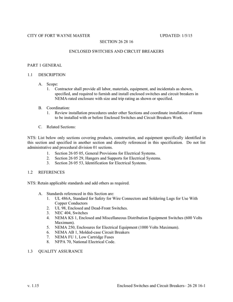
CITY OF FORT WAYNE MASTER UPDATED: 1/5/15 SECTION 26 28 16 ENCLOSED SWITCHES AND CIRCUIT BREAKERS PART 1 GENERAL 1.1 DESCRIPTION A. Scope: 1. Contractor shall provide all labor, materials, equipment, and incidentals as shown, specified, and required to furnish and install enclosed switches and circuit breakers in NEMA-rated enclosure with size and trip rating as shown or specified. B. Coordination: 1. Review installation procedures under other Sections and coordinate installation of items to be installed with or before Enclosed Switches and Circuit Breakers Work. C. Related Sections: NTS: List below only sections covering products, construction, and equipment specifically identified in this section and specified in another section and directly referenced in this specification. Do not list administrative and procedural division 01 sections. 1. Section 26 05 05, General Provisions for Electrical Systems. 2. Section 26 05 29, Hangers and Supports for Electrical Systems. 3. Section 26 05 53, Identification for Electrical Systems. 1.2 REFERENCES NTS: Retain applicable standards and add others as required. A. Standards referenced in this Section are: 1. UL 486A, Standard for Safety for Wire Connectors and Soldering Lugs for Use With Copper Conductors 2. UL 98, Enclosed and Dead-Front Switches. 3. NEC 404, Switches 4. NEMA KS 1, Enclosed and Miscellaneous Distribution Equipment Switches (600 Volts Maximum). 5. NEMA 250, Enclosures for Electrical Equipment (1000 Volts Maximum). 6. NEMA AB 1, Molded-case Circuit Breakers 7. NEMA FU 1, Low Cartridge Fuses 8. NFPA 70, National Electrical Code. 1.3 QUALITY ASSURANCE v. 1.15 Enclosed Switches and Circuit Breakers– 26 28 16-1 A. Regulatory Requirements: NTS: Retain applicable regulations and add others as required. 1. NEC Article 404, Switches. 2. Enclosed switches and circuit breakers shall bear the UL label. 3. National Electrical Code (NEC): Components and installation shall comply with National Fire Protection Association (NFPA) 70. 1.4 B. Testing Agency Qualifications: In addition to requirements specified in Section 26 01 26 independent testing agency shall meet OSHA criteria for accreditation of testing laboratories, Title 29, Part 1907, or shall be full member company in InterNational Electrical Testing Association. C. Manufacturer: 1. Manufacturer shall have not less than five years of experience producing substantially similar equipment to that required and, upon request, shall submit documentation of not less than five installations in satisfactory operation for not less than five years in the United States. 2. Enclosed switches, fuses and circuit breakers shall be product of single manufacturer. SUBMITTALS A. Submit the following: 1. Shop Drawings: a. Listing of each switch to be furnished, including location, rating, and NEMA enclosure type for each. b. Outline drawings with dimensions, materials of construction, installation details, accessories, and equipment ratings for voltage, amperage and short-circuit. c. Wiring diagrams detailing power and control wiring and differentiating clearly between manufacturer-installed wiring and field-installed wiring. 2. Product Data: a. Manufacturer’s technical information for enclosed switches and circuit breakers proposed for use including, but not limited too descriptive data and time-current curves for protective devices and let-through current curves for those devices with current-limiting characteristics. Include coordination charts and tables, fuse size for elevator feeder and disconnect applications and related data 3. Certifications: a. Manufacturer’s certification of completed installation. 4. Source Quality Control Submittals: a. Results of required source quality control tests and inspections. 5. Site Quality Control Submittals: a. Results of required field quality control tests and inspections. 6. Qualifications Statements: a. Submit manufacturer qualifications when requested by Engineer. 7. Operation and Maintenance Data: a. Submit complete installation, operation and maintenance manuals including test reports, maintenance data and schedules, and description of operation. v. 1.15 Enclosed Switches and Circuit Breakers– 26 28 16-2 b. c. Recommended Spare Parts and Extra Stock Materials: Include list of additional spare parts or extra stock materials recommended for use with enclosed molded-case circuit breakers. Describe each recommended part, quantity recommended, current unit price, and ordering information. Comply with Section 01 78 23, Operations and Maintenance Data. NTS: Delete paragraph “8” if not required. 8. Spare Parts: a. Furnish one set of spare fuses for each fused disconnect switch to be installed. PART 2 PRODUCTS 2.1 ENCLOSED SWITCH MANUFACTURERS A. Manufacturers: Provide products of one of the following: 1. Square-D Company. 2. Cutler-Hammer. NTS: Edit below to suit the Project. 2.2 ENCLOSED SWITCH MATERIALS A. Service Disconnect Switches: 1. Type: Fused, heavy-duty, single throw, quick-make, quick-break mechanism, visible blades in “OFF” position and safety handle. 2. Rating: Voltage, current and short circuit ratings and number of poles as shown or indicated on the Drawings. Switch shall bear UL label indicating suitability for use as service equipment and shall comply with UL 98, NEMA KS 1, and NEMA 250. NTS: Delete paragraph “3” if not required. 3. Provide auxiliary dry contacts to indicate switch position where shown on the Drawings. B. Single Throw, Circuit Disconnect Switches: 1. Type: Fused or unfused, horsepower rated, heavy-duty, single throw, quick- make, quick-break mechanism, visible blades in the "OFF" position and safety handle. 2. Rating: Voltage and current ratings and number of poles as required for motor or equipment circuits being disconnected. Switches shall bear a UL label and shall comply with the requirements of UL 98, NEMA KS 1 and NEMA 250. NTS: Delete paragraph “3” if not required. Some VFD manufacturers require an auxiliary contact to be wired to disable the drive to avoid potential VFD damage from opening the output leads while the drive is running. Coordinate with and edit section 26 29 23, low-voltage variable frequency drives, accordingly. 3. Provide auxiliary dry contacts to indicate switch position. C. v. 1.15 Double Throw Safety Switches: Enclosed Switches and Circuit Breakers– 26 28 16-3 1. 2. Type: Fused, double throw with center “OFF” position, quick-make, quick-break mechanism, visible blades in the “OFF” position, and safety handle. Rating: Service Entrance Rated, voltage and current ratings and number of poles as required for circuits being disconnected. Switches shall bear UL label and shall comply with UL 98, NEMA KS 1, and NEMA 250. NTS: Delete paragraph “3” if not required. 3. Provide auxiliary dry contacts to indicate switch position where shown on the Drawings. D. Enclosure: NEMA KS 1, Type 12, unless specified or required otherwise to meet environmental conditions of installed location. 1. Outdoor or Other Wet or Damp Indoor Locations: NEMA Type 4X 316 stainless steel 2. Hazardous Areas Indicated on Drawings: NEMA Type 7C. E. 2.3 Identification: 1. Identify enclosures in accordance with Section 26 05 53, Identification for Electrical Systems. 2. Provide nameplate to identify the equipment served by enclosed switch and associated source of power. CARTRIDGE FUSES A. Characteristics: NEMA FU 1, nonrenewable cartridge fuse; class as specified or indicated; current rating as indicated; voltage rating consistent with circuit voltage. 2.4 ENCLOSED CIRCUIT BREAKERS A. Manufacturer: Provide equipment by one of the following: 1. Eaton Cutler Hammer 2. Square-D B. Enclosed Molded-Case Circuit Breaker: NEMA AB 1, handle lockable with 2 padlocks. C. Characteristics: 1. Frame size, trip rating, number of poles, and auxiliary devices as indicated 2. Interrupting capacity rating to meet available fault current, 10,000 symmetrical rms amps minimum 3. Appropriate application listing when used for switching fluorescent lighting loads or heating, air conditioning, and refrigeration equipment. D. Interchangeable Trips: Circuit breakers, 200 amps and larger, with trip units interchangeable within frame size. E. Field-Adjustable Trips: Circuit breakers, 400 amps and larger, with adjustable short time and continuous current settings. F. Current-Limiting Trips: Where indicated, let-through ratings less than NEMA FU 1, Class RK-5. v. 1.15 Enclosed Switches and Circuit Breakers– 26 28 16-4 G. Current Limiters: Where indicated, integral fuse listed for circuit breaker. H. Molded-Case Switch: Where indicated, molded-case circuit breaker without trip units. I. Lugs: Mechanical lugs and power-distribution connectors for number, size, and material of conductors indicated. J. Shunt Trip: Where indicated, 120 volts, 60 Hz. K. Accessories: Provide normally open auxiliary contact for remote monitoring by the PLC for all motors, gates, valves, and other devices as specified. L. 2.5 Enclosure: NEMA AB 1, Type 12, unless specified or required otherwise to meet environmental conditions of installed location. 1. Outdoor or Other Wet or Damp Indoor Locations: NEMA Type 316 4X stainless steel 2. Hazardous Areas Indicated on Drawings: NEMA Type 7C. SOURCE QUALITY CONTROL A. Tests: 1. Perform standard factory tests on equipment furnished under this Section. Tests shall be in accordance with applicable NEMA and UL standards. PART 3 EXECUTION 3.1 INSPECTION A. Examine conditions under which the Work will be installed and notify Engineer in writing of conditions detrimental to proper and timely completion of the Work. Do not proceed with the Work until unsatisfactory conditions are corrected. 3.2 ENCLOSED SWITCH AND CIRCUIT BREAKER INSTALLATION A. Install in accordance with NFPA 70, and Laws and Regulations. B. Mounting and Installation: 1. Install equipment to provide sufficient access and working space for ready and safe operation and maintenance. Equipment centerline shall not be less than four feet above finished floor. 2. Securely fasten equipment to walls or other surfaces on which equipment is mounted. Provide independent supports complying with Section 26 05 29 Hangers and Supports for Electrical Systems, where there is no wall or other surface capable of supporting the equipment. 3. Provide suitable 1/4-inch spacers to prevent mounting enclosure directly against walls. C. Adjustments: Perform field adjustments of circuit breakers as required to place equipment in operating condition. Adjustable breaker settings shall be in accordance with the accepted v. 1.15 Enclosed Switches and Circuit Breakers– 26 28 16-5 power distribution coordination study prepared under Section 26 05 73, Electrical Power Distribution System Studies, or as directed by Engineer. D. Install circuit breakers in locations as indicated, according to manufacturer's written instructions. E. Install enclosed switches and circuit breakers level and plumb. F. Install wiring between enclosed switches and circuit breakers and control/indication devices. G. Connect enclosed switches and circuit breakers and components to wiring system and to ground as indicated and instructed by manufacturer. Tighten connectors and terminals, including screws and bolts according to equipment manufacturer's published torque tightening values for equipment connectors. Where manufacturer's torquing requirements are not indicated, tighten connectors and terminals according to tightening torques specified in UL Standard 486A. 3.3 FUSE APPLICATIONS A. Main Service: Class L, fast acting. B. Main Feeders: Class J, time delay. C. Motor Branch Circuits: Class RK1, time delay. D. Other Branch Circuits: Class RK5, non-time delay. 3.4 IDENTIFICATION A. Install typewritten labels on inside door of each fused switch to indicate fuse replacement information. 3.5 COORDINATION STUDY A. Where coordination study recommends changes in types, classes, features or ratings of equipment or devices specified in Section 26 02 20 from those indicated, make written request for instructions. Obtain instructions from ENGINEER before ordering equipment or devices recommended to be changed. 3.6 FIELD QUALITY CONTROL A. Field Tests and Inspections: 1. All test equipment and material shall be by Contractor. 2. Perform visual and mechanical inspection including: a. Inspect for physical, electrical, and mechanical condition. b. Check for proper installation, required area clearances, physical damage and proper alignment. c. Check electrical and mechanical interlock systems for proper operation. d. Clean and lubricate as required. v. 1.15 Enclosed Switches and Circuit Breakers– 26 28 16-6 e. B. Other testing and inspections recommended by manufacturer. Manufacturer’s Services: 1. Provide services of qualified, factory-trained manufacturer’s representative to advise Contractor on installation of the equipment and to check the installed equipment prior to start-up. 2. Qualified factory-trained manufacturer’s representative shall certify in writing that equipment has been installed, adjusted, and tested in accordance with manufacturer’s recommendations. NTS: Coordinate training requirements with section 01 79 23, Instruction of Operations and Maintenance Personnel. 3. Furnish services of qualified trained specialist, with minimum of five years experience, from manufacturer to instruct Owner’s operations and maintenance personnel in recommended operation and maintenance of the equipment. Training requirements, duration of instruction, and other requirements shall be in accordance with Section 01 79 23, Instruction of Operations and Maintenance Personnel. 3.7 ADJUSTING NTS: Coordinate adjusting requirements with Owner. Edit section below if 26 02 20 Electrical Power System Study is not included in Project. A. Set field-adjustable pick-up and time-sensitivity ranges in accordance with Section 26 02 20. 3.8 CLEANING A. Upon completion of installation, inspect enclosed switch or circuit breakers. Remove paint splatters and other spots, dirt, and debris. Touch up scratches and mars of finish to match original finish. + + END OF SECTION + + v. 1.15 Enclosed Switches and Circuit Breakers– 26 28 16-7
